Polarizing plate, liquid crystal display using the polarizing plate and method of fabricating the polarizing plate

Active Publication Date: 2015-08-06
SAMSUNG DISPLAY CO LTD
View PDF5 Cites 4 Cited by
  • Summary
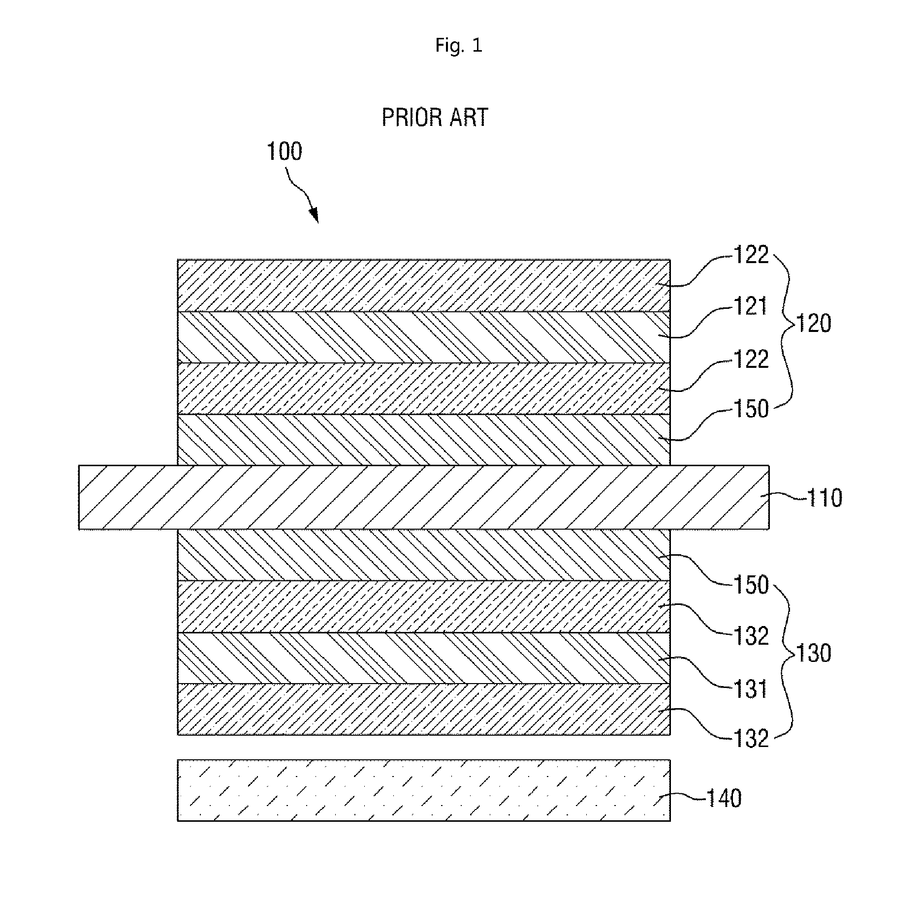
  • Abstract
  • Description
  • Claims
  • Application Information

AI Technical Summary

Benefits of technology

[0015]According to one or more exemplary embodiment, bending of a polarizing plate even under high-temperature, high-humidity conditions is reduced or effectively prevented to secure

Problems solved by technology

However, the TAC films have relatively high moisture permeability, and may thus cause the polar

Method used


Image

  • Polarizing plate, liquid crystal display using the polarizing plate and method of fabricating the polarizing plate
  • Polarizing plate, liquid crystal display using the polarizing plate and method of fabricating the polarizing plate
  • Polarizing plate, liquid crystal display using the polarizing plate and method of fabricating the polarizing plate

Examples


Embodiment Construction

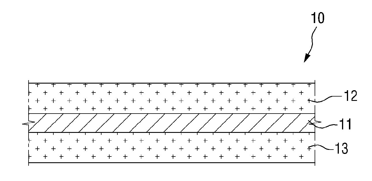
[0030]Advantages and features of the invention and methods of accomplishing the same may be understood more readily by reference to the following detailed description of exemplary embodiments and the accompanying drawings. The invention may, however, be embodied in many different forms and should not be construed as being limited to the exemplary embodiments set forth herein. Rather, these exemplary embodiments are provided so that this disclosure will be thorough and complete and will fully convey the invention to those skilled in the art, and the invention will only be defined by the appended claims. Like reference numerals refer to like elements throughout the specification.

[0031]The terminology used herein is for the purpose of describing particular embodiments only and is not intended to be limiting of the invention. As used herein, the singular forms “a,”“an” and “the” are intended to include the plural forms as well, unless the context clearly indicates otherwise. It will be ...


PUM

PropertyMeasurementUnit
Thicknessaaaaaaaaaa
Thicknessaaaaaaaaaa
Surface roughnessaaaaaaaaaa

Abstract

A polarizing plate includes a first glass plate; a second glass plate facing the first glass plate; and a polarizing device between the first and second glass plates. An external surface of at least one of the first and second glass plates, which is not in contact with the polarizing device, has a root mean square surface roughness of about 1 nanometer or less.

Description

[0001]This application claims priority to Korean Patent Application No. 10-2014-0013104 filed on Feb. 5, 2014, and all the benefits accruing therefrom under 35 U.S.C. §119, the disclosure of which is incorporated herein by reference in its entirety.BACKGROUND[0002]1. Field[0003]Exemplary embodiments relate to a polarizing plate, a liquid crystal display (“LCD”) including the polarizing plate and a method of fabricating the polarizing plate.[0004]2. Description of the Related Art[0005]Polarizing plates are commonly used in LCDs to control the vibration direction of light and thus to visualize a display pattern of the LCDs. LCDs boast of their wide range of application, ranging from small devices to laptop computers, LCD monitors, LCD color projectors, LCD televisions (“TVs”), navigation systems for automobiles, personal phones and various measuring equipment for indoor and outdoor use. Particularly, LCD monitors and LCD TVs often use relatively high-luminance backlight units to provi...

Claims


Application Information

Patent Timeline
IPC IPC(8): G02F1/1335B32B38/00B32B37/18B32B38/14G02B5/30G02B1/18
CPCG02F1/13362G02B5/3025G02B1/18B32B37/18B32B2457/202B32B38/0012B32B2038/0028B32B2551/00B32B38/14B32B2038/0076B32B2307/42B32B2315/08G02B5/3033G02B1/14G02F1/133528Y10T156/10
Inventor KIM, JONG SEONGKIM, SANG IL
Owner SAMSUNG DISPLAY CO LTD
Why Eureka
Try Eureka