Power holdup circuit

a power holdup circuit and power technology, applied in emergency power supply arrangements, electrical equipment, instruments, etc., can solve the problems of reducing the power factor of the system, reducing the useful power of the system, and reducing the useful power of the reactive power, so as to achieve a low design complexity and high power factor

a power holdup circuit and power technology, applied in emergency power supply arrangements, electrical equipment, instruments, etc., can solve the problems of reducing the power factor of the system, reducing the useful power of the system, and reducing the useful power of the reactive power, so as to achieve a low design complexity and high power factor

US6879140B2Inactive Publication Date: 2005-04-12MKS INSTR INC

Image

  • Power holdup circuit
  • Power holdup circuit
  • Power holdup circuit

Examples


Embodiment Construction

CRIPTION OF THE DRAWINGS

[0022]The present invention will become fully understood from the detailed description and the accompanying drawings, wherein:

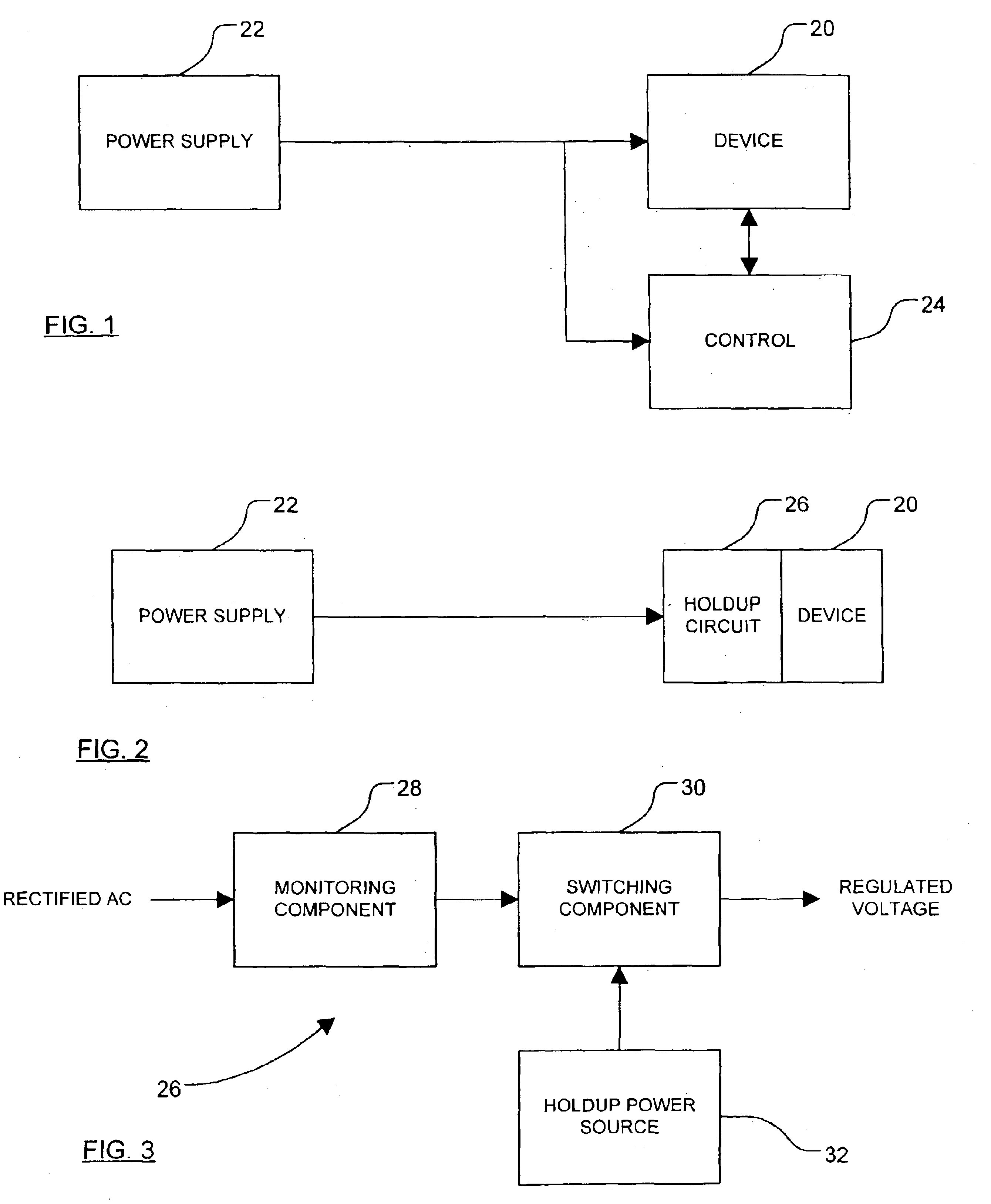
[0023]FIG. 1 is a simplified block diagram of a known system for providing power factor correction;

[0024]FIG. 2 is a simplified block diagram of a system having a holdup circuit constructed according to the principles of the present invention therein;

[0025]FIG. 3 is a simplified block diagram of a holdup circuit of the present invention;

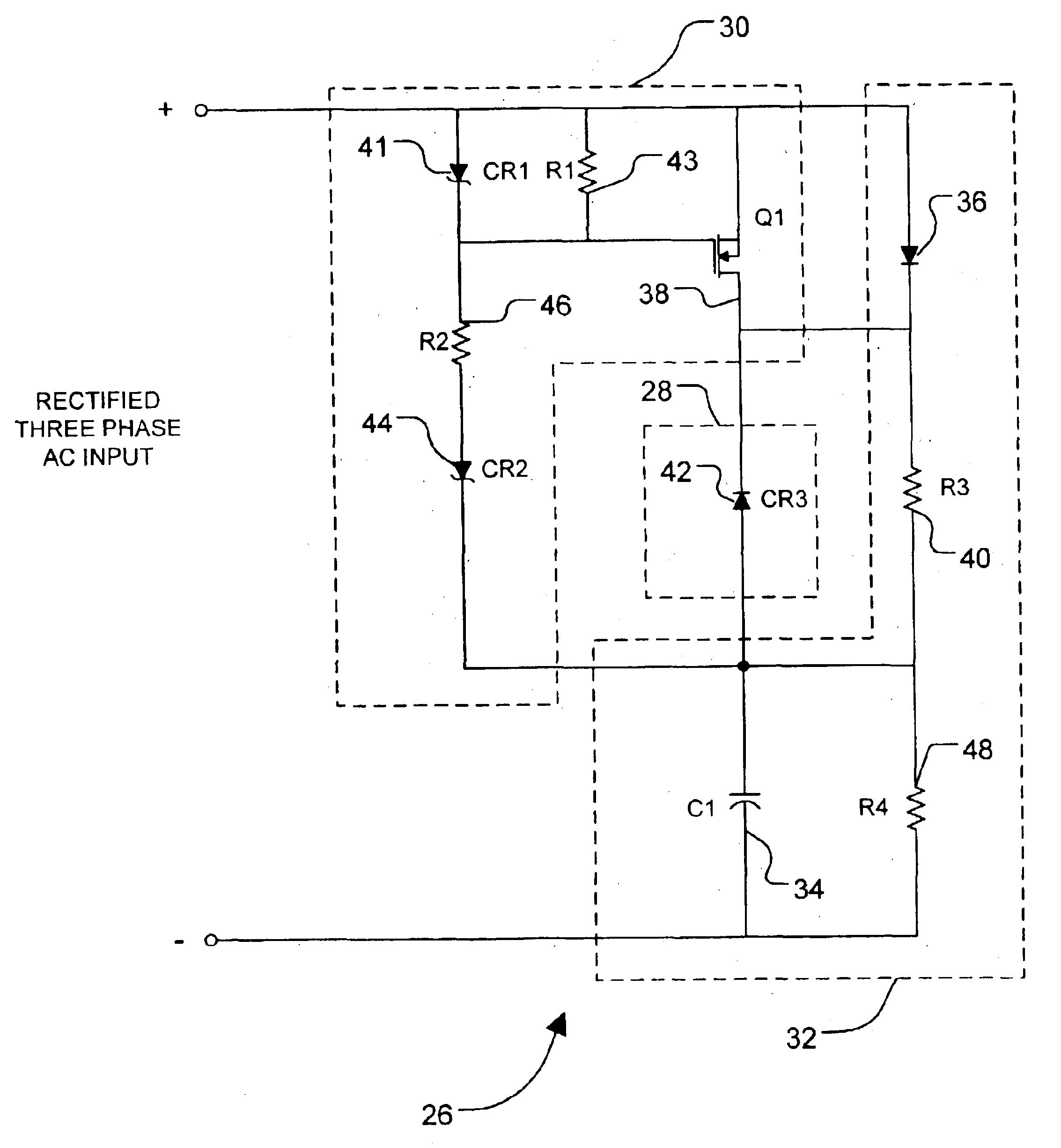
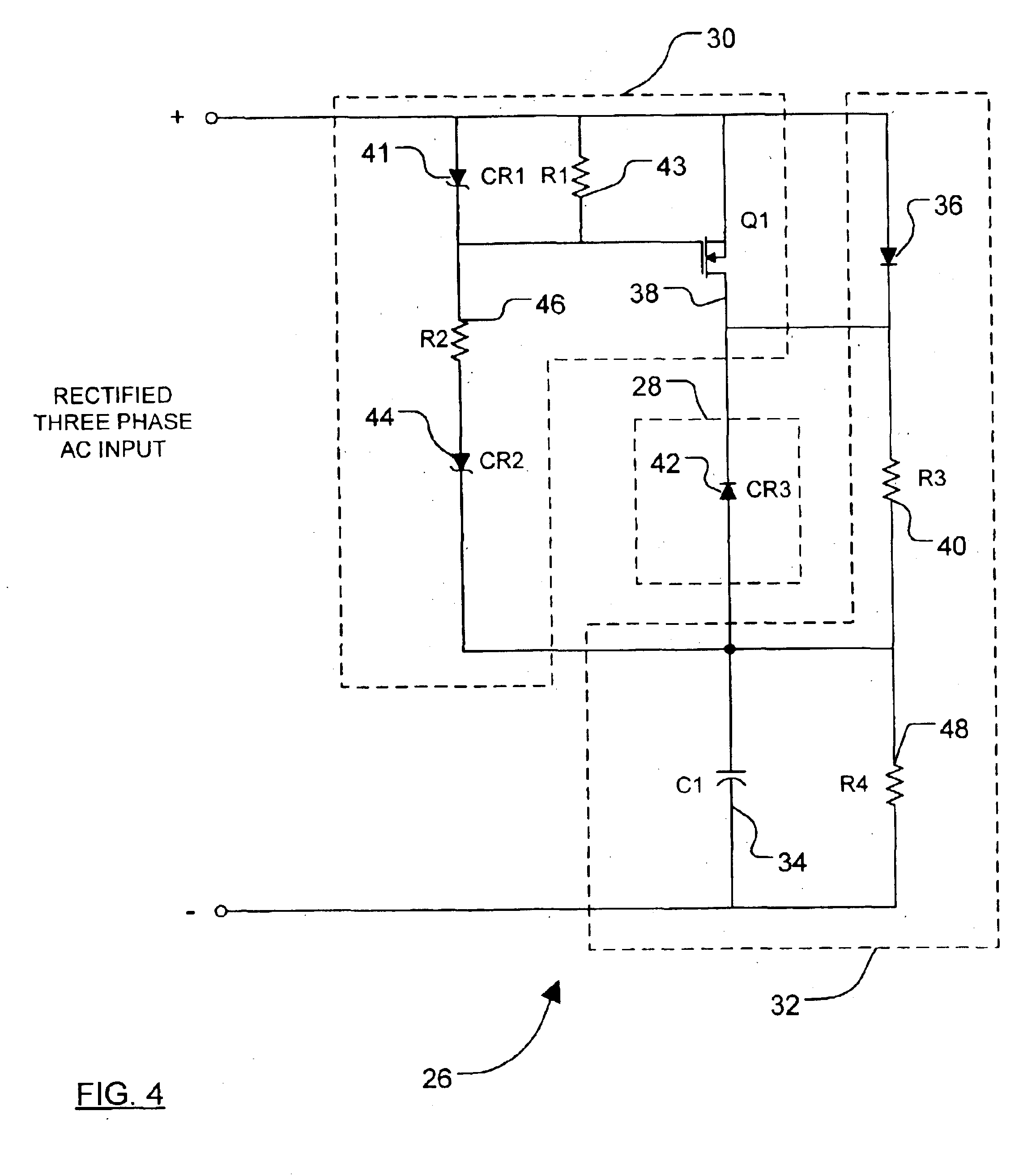
[0026]FIG. 4 is a schematic diagram of a holdup circuit of the present invention; and

[0027]FIG. 5 is a schematic diagram of another embodiment of a holdup circuit arranged in accordance with the principles of the present invention.

DETAILED DESCRIPTION

[0028]The following description of the present invention is merely exemplary in nature and is in no way intended to limit the invention, its application, or uses. Thus, although the application of the present invention as disclosed herein is generally direc...


PUM


Abstract

A power holdup circuit including a monitoring circuit and a power holdup circuit. The monitoring circuit includes an average voltage comparator and an absolute voltage comparator which cooperate to detect a voltage drop in the voltage supplied by the power supply. The monitoring circuit also includes a timer to determine the time period of the voltage dropout. If a predetermined voltage dropout event occurs, the monitoring circuit generates a control signal to a switching component which activates a holdup power source. The holdup power source includes an energy storage device that stores energy to maintain the supply voltage during dropout periods.

Description

CROSS-REFERENCE TO RELATED APPLICATIONS[0002]This application is a continuation-in-part of U.S. patent application Ser. No. 10 / 255,425 filed on Sep. 26, 2002. The disclosure of the above application is incorporated herein by reference.FIELD OF THE INVENTION[0003]The present invention relates generally to systems for controlling line voltage, and more particularly to a circuit for maintaining power during line voltage dropouts in, for example, power conversion equipment.BACKGROUND OF THE INVENTION[0004]Power factor relates generally to the efficiency of a system in using power and is preferably maintained at a high level (i.e., 0.9 or higher) to minimize losses. In particular, power factor defines the relationship between the actual / active or real power being used by the system (i.e., measured in kilo-Watts (KW)) and the total power supplied and available to the system. Further, total power is defined by apparent power (i.e., measured in volt-amps (VA)), which includes a non-working ...

Claims


Application Information

Patent Timeline
12 Apr 2005
Publication
US6879140B2
IPC
H02J9/06
CPC
H02J9/061
Inventors
ELKIN, IGOR; BYSTRYAK, ILYA