Structure for supporting sign board

a sign board and structure technology, applied in the field of sign boards, can solve the problems of unfavorable productivity, compatibility and production cost, unfavorable product quality, and inability to appropriately cope with the change of the diameter of the post “p”, and achieve the effects of easy installation, simple operation, and excellent corrosion resistan

Inactive Publication Date: 2005-04-19
HYNYANG FRAME CO LTD
View PDF16 Cites 14 Cited by
  • Summary
  • Abstract
  • Description
  • Claims
  • Application Information

AI Technical Summary

Benefits of technology

[0015]Accordingly, the present invention has been made keeping in mind the above problems occurring in the prior art, and an object of the present invention is to provide a structure for supporting a sign board, which allows the sign board to be easily and stably installed on a post, regardless of a size and a shape of the post.
[0016]Another object of the present invention is to provide a structure for supporting a sign board, which allows one or more sign boards to be installed on a post by means of one band clamp if necessary.
[0017]A further object of the present invention is to provide a structure for supporting a sign board, which maximizes a functional area of the sign board to improve effectiveness of the sign board.

Problems solved by technology

However, since the conventional band clamp 2 is designed to have a certain diameter, the band clamp 2 cannot appropriately cope with changes of the diameter of the post “P”.
This is unfavorable in terms of productivity, compatibility and production cost.
In this case, the installation operation of the sign boards is considerably complicated, and production cost is increased and a cityscape is significantly deteriorated.
Furthermore, since the sign board 5 is partially interrupted by the hinge brackets 6, the functional area of the sign board 5 is reduced, thereby reducing its effectiveness.
Though the respective components are manufactured by iron material and then coated with paint, the components are apt to be oxidized and corroded due to paint damage at their coupled portions after a long time period, thereby causing contamination of the post “P” and reduction of service life of the post “P”.

Method used


Image

  • Structure for supporting sign board
  • Structure for supporting sign board
  • Structure for supporting sign board

Examples


Embodiment Construction

[0036]This invention will be described in further detail by way of example with reference to the accompanying drawings.

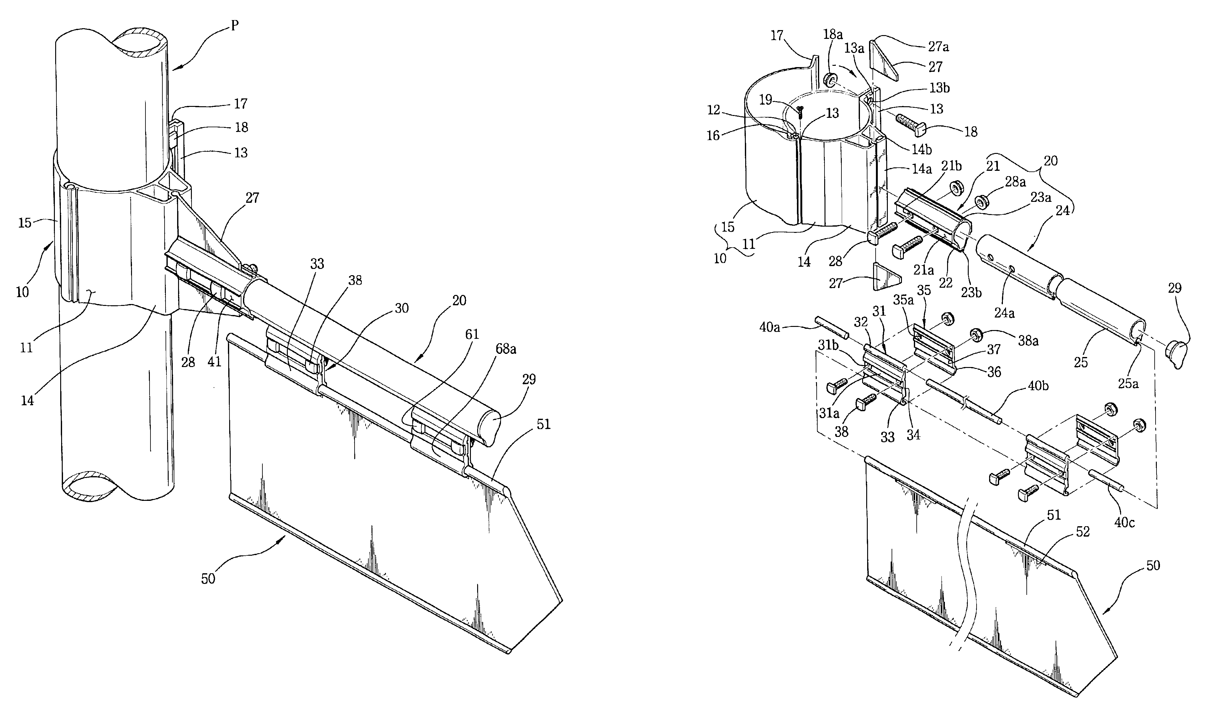
[0037]As shown in FIGS. 3 to 6, a structure for supporting a sign board according to the present invention includes a post clamp 10 mounted on a post “P” installed on a roadside, a hanger 20 radially coupled to the post clamp 10 to be horizontally positioned, and connectors 30 for connecting a sign board exhibiting traffic information to the hanger 20.

[0038]The post clamp 10 includes a pair of semicircular clamping bands 11 and 15, which are hingedly coupled to each other at their ends and fastened by bolts 18 and nuts 18a at their other ends.

[0039]As shown in FIG. 7, the first clamping band 11 is provided at its end with a hinge groove 12 having a C-shaped cross section. The first clamping band 11 is further provided adjacent to the hinge groove 12 with a screw groove 11a having a C-shaped cross section, so that the screw groove 11a is engaged with retaining screws...


PUM


Abstract

A structure for supporting a sign board is disclosed. The structure includes: a post clamp having a pair of arched clamping bands which are hingedly coupled and joined to each other by a fastening element, at least one clamping band having a pillar; a hanger having a socket pipe joined to the pillar of the post clamp, a support bar inserted into the socket pipe and joined by a fastening element, the support bar having an axial coupling groove; at least one connector having a first coupling plate with a coupling bulge adapted to be fitted into the coupling groove of the support bar and with a first arched hinge holder, and a second coupling plate coupled to the first coupling plate having a second arched hinge holder; and a sign board having a coupling bulge and a guide slot through which the hinge holders of the connector pass.

Description

[0001]This application claims the benefit of Korean Utility Model Application No. 2001-0031600, which was filed in the Korean Intellectual Property Office, Republic of Korea, on Oct. 6, 2001.BACKGROUND OF THE INVENTION[0002]1. Field of the Invention[0003]The present invention relates to a sign board installed on a roadside to exhibit information regarding roads, buildings or street names for convenience of drivers or pedestrians, and more particularly to a structure for supporting a sign board showing driving or walking information, which allows the sign board to be easily and stably attached to a post and which provides an acceptable appearance of the sign board and the post.[0004]2. Description of the Prior Art[0005]In general, various road guide signs, which are intended to show drivers and pedestrians information relating to dangerous circumstances of a road to assure safety and smooth driving conditions, and which are further intended to provide drivers and pedestrians with inf...

Claims


Application Information

Patent Timeline
Patent Type & Authority Patents(United States)
IPC IPC(8): G09F7/18G09F7/22E01F9/623E01F9/658E01F9/669E01F9/677E01F9/681E01F9/696
CPCG09F7/22
Inventor KIM, YONG SOO
Owner HYNYANG FRAME CO LTD
Why Eureka
Try Eureka