Corner tie bracket for use with insulated concrete form systems

a technology of insulated concrete and corner tie brackets, which is applied in the direction of walls, building components, pillars, etc., can solve the problems of not providing sufficient surface area and/or spacing for proper flanges, blowing out of corner foam panels, etc., and achieves the effect of improving the structural load carrying capacity of the corner tie bracket, increasing the flexibility of attachment options, and increasing the number of attachment options

Inactive Publication Date: 2008-07-03
AIRLITE PLASTICS
View PDF13 Cites 7 Cited by
  • Summary
  • Abstract
  • Description
  • Claims
  • Application Information

AI Technical Summary

Benefits of technology

[0007]The corner tie bracket of the present invention overcomes the weaknesses and disadvantages associated with prior art designs and teaches a more versatile and stronger corner tie bracket design. The present corner tie bracket includes a pair of corner side members connected to a structural web member, the corner side members sharing a common end and extending substantially perpendicularly from each other, each bracket side member including a pair of spaced apart flanges adapted for receiving and holding exterior siding or facade which may be attached thereto. These corner side flanges extend in the vertical direction and are of sufficient height, width and thickness so as to serve as a stud to which exterior facades can be anchored. A concrete engaging member extends outwardly away from the structural web member and is offset from the common end portion or joinder of the pair of corner bracket side members. The concrete engaging member extends inwardly across the space formed by and between the two ICF panels forming the corner block and includes a free end portion which is completely encapsulated within the inner corner panel member at its corner. In similar fashion, the corner brack

Problems solved by technology

However, since the known corner tie brackets often times either do not include any type of concrete engaging member, or such concrete engaging member does not extend all the way across the space formed by and between the pair of foam panels forming the corner block at the corner, such known corner tie brackets are not anchored or embedded within the inner corner panel at its corner.
Due to the forces generated by the flowing fluid concrete during the pouring process, blow out of the corner foam pan

Method used


Image

  • Corner tie bracket for use with insulated concrete form systems
  • Corner tie bracket for use with insulated concrete form systems
  • Corner tie bracket for use with insulated concrete form systems

Examples


Embodiment Construction

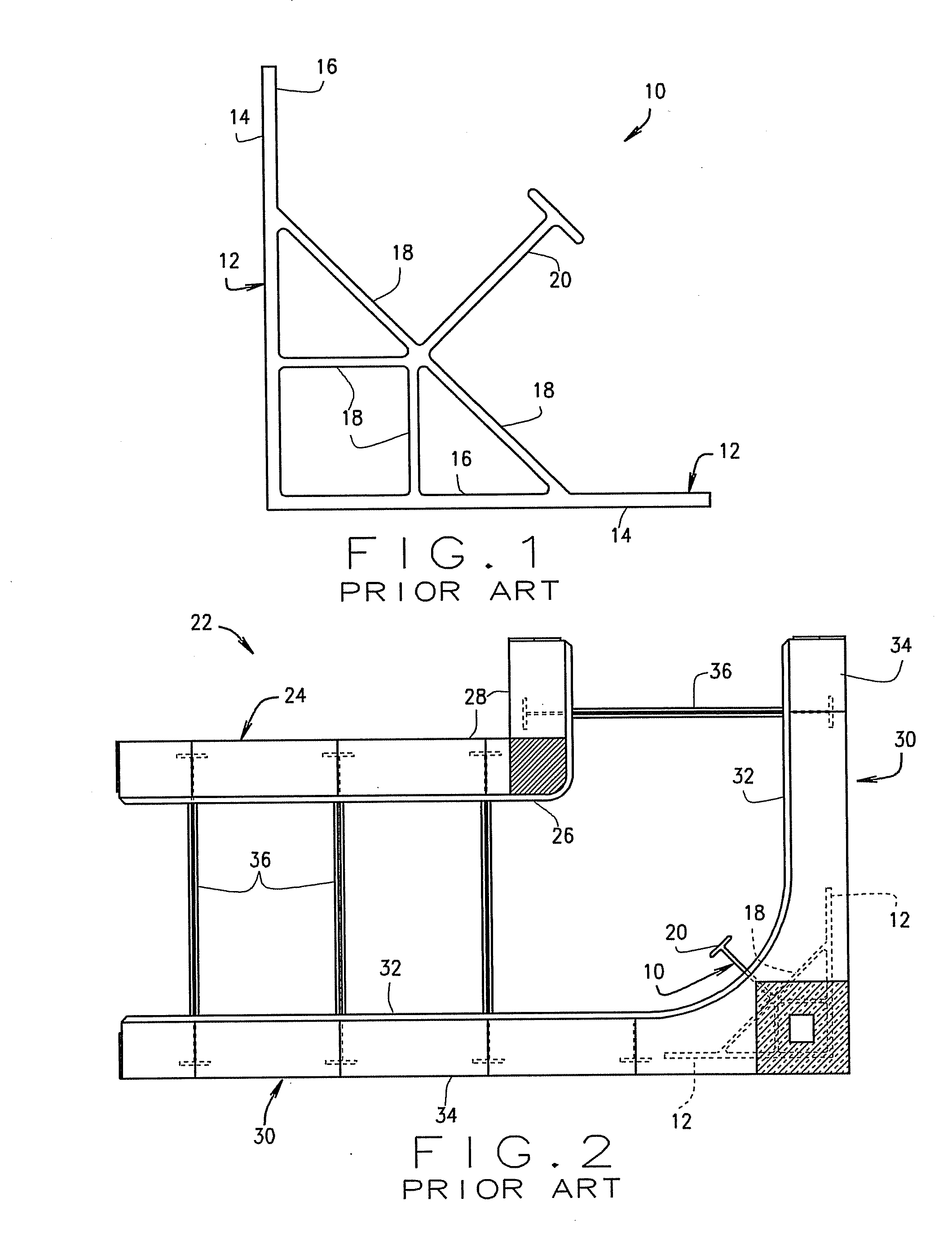
[0017]FIG. 1 illustrates a typical prior art corner tie bracket 10 having a pair of flange members 12 sharing a common end and extending perpendicularly from each other, each flange member 12 having an outer surface 14 and an inner surface 16. An array of web members 18 connects the inner surfaces 16 of each flange 12. A concrete engaging member 20 extends inwardly from the web 18 at substantially a 45° angle from either flange 12.

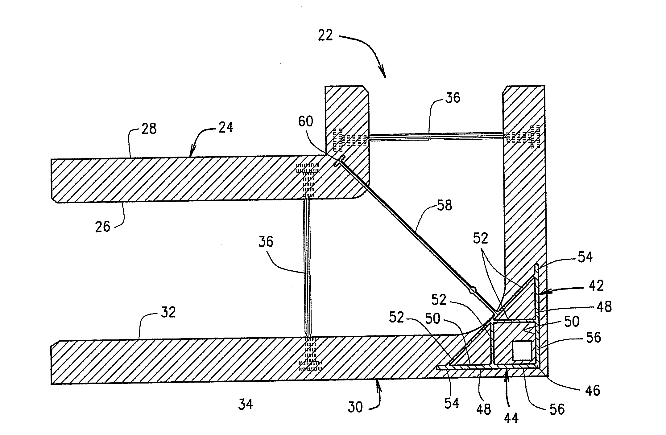
[0018]A typical corner ICF block 22 is illustrated in FIG. 2 and includes an inner corner panel 24 having an inner surface 26 and an outer surface 28, an outer corner panel 30 having an inner surface 32 and an outer surface 34, and a plurality of conventional ties 36 having opposed flange portions encapsulated within a respective panel 24 and 30, thereby holding and retaining the corner panels 24 and 30 in opposing fashion. The corner block 22 may include any type of engaging means formed along respective opposed longitudinal and vertical edges for removab...


PUM


Abstract

A corner bracket member for use in an Insulated Concrete Form (ICF) corner block or other form assembly having a pair of opposed inner and outer spaced apart panels for receiving concrete therebetween, the corner bracket member including at least a pair of side members, each side member having at least a pair of spaced apart flange members adapted for receiving and anchoring exterior facade or other surfaces thereto, and at least one concrete engaging member positioned and located so as to extend in a direction completely across the space formed by and between the inner and outer panels associated with the ICF corner block. The side members and flange members of the corner bracket member are encapsulated within one of the inner and outer panels and the at least one concrete engaging member includes a terminal end portion which is encapsulated within the other of the inner and outer panels when attached thereto.

Description

CROSS-REFERENCE TO RELATED APPLICATION[0001]This application claims the benefit of U.S. Provisional Patent Application No. 60 / 882,006, filed on Dec. 27, 2006, the disclosure of which is incorporated herein by reference.BACKGROUND OF INVENTION[0002]The present invention relates to Insulated Concrete Form systems utilizing foam block forms and, more particularly, to an improved corner tie bracket for use in a wide variety of different types of Insulating Concrete Form (ICF) systems.[0003]Insulating Concrete Form (ICF) systems are known and serve to both contain fluid concrete while it solidifies and provide insulation for the finished structure. Such systems utilize a plurality of individual units, panels or blocks aligned horizontally and vertically in an interlocking arrangement to create forms for concrete walls. Each block typically includes a pair of foam panels which are retained in a spaced relationship parallel to each other by a plurality of spaced apart ties which include op...

Claims


Application Information

Patent Timeline
IPC IPC(8): E04B1/16
CPCE04B2002/867E04B2/8617
Inventor PFEIFFER, HENRY E.
Owner AIRLITE PLASTICS
Why Eureka
Try Eureka