
Foot structure of a rack for holding spray nozzles

a technology for spray nozzles and racks, applied in the field of racks for spray nozzles, can solve the problems of defective design of the rack described abov

Inactive Publication Date: 2005-04-19
SHIN TAI SPURT WATER OF THE GARDEN TOOLS
View PDF28 Cites 13 Cited by
  • Summary
  • Abstract
  • Description
  • Claims
  • Application Information

AI Technical Summary

Benefits of technology

[0009]The features and the advantages of the present invention will be more readily understood upon a thoughtful deliberation of the following detailed description of two preferred embodiments of the present invention with reference to the accompanying drawings.

Problems solved by technology

The prior art rack described above is defective in design in that it is integrally made of a plastic material by injection molding and is therefore apt to slide easily by itself.

Method used


Image

  • Foot structure of a rack for holding spray nozzles
  • Foot structure of a rack for holding spray nozzles
  • Foot structure of a rack for holding spray nozzles

Examples


Embodiment Construction

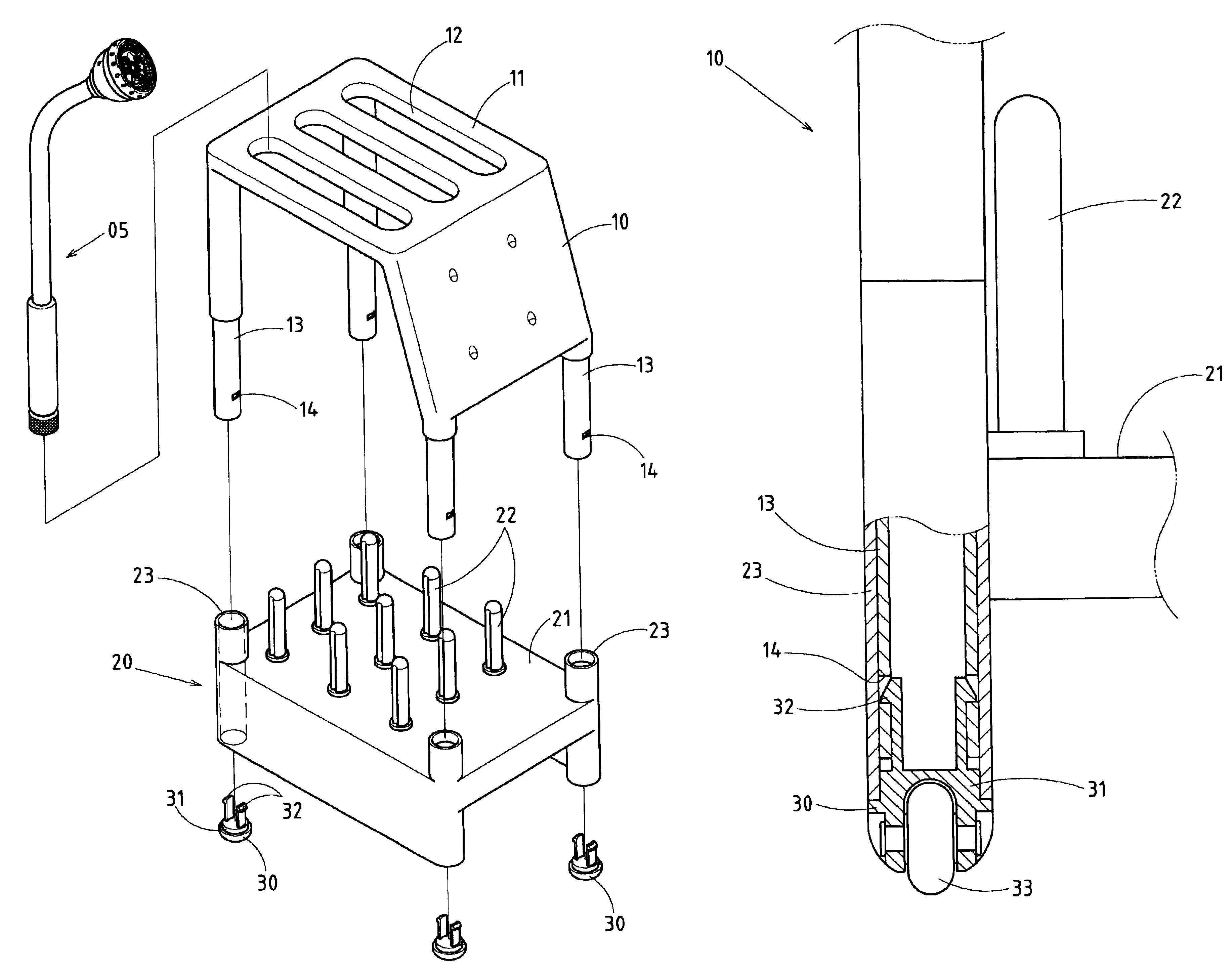
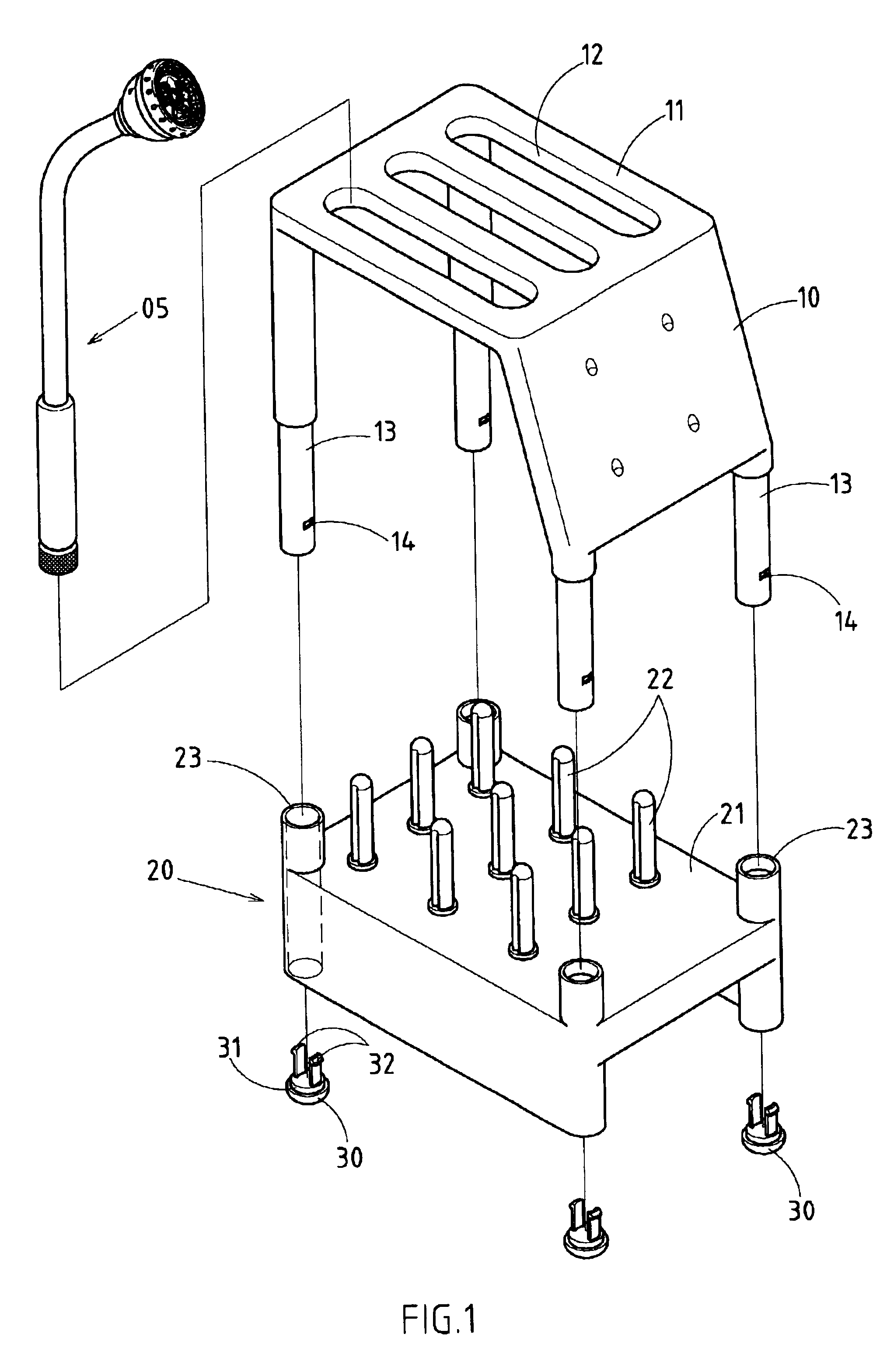
[0015]As shown in FIGS. 1 and 2, a rack embodied in the present invention is used to hold a plurality of spray nozzles 05 and is formed of a top frame 10 and a bottom frame 20.

[0016]The top frame 10 is formed of a plate 11 and four legs 13. The plate 11 is provided with a plurality of through slots 12. The legs 13 are provided in proximity of a bottom end with two retaining slots 14 opposite to each other.

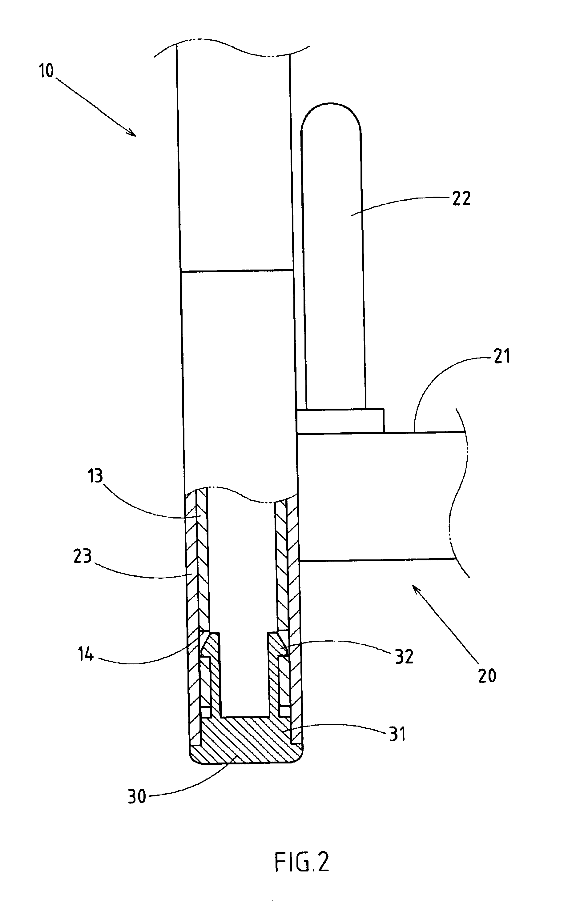
[0017]The bottom frame 20 is provided with plate 21, four support rods 53 and four feet 30. The plate 21 is provided in the upper side with a plurality of upright pillars 22 corresponding in location to the through slots 12 of the top frame 10. The upright pillars 22 are used to locate the barrels of the spray nozzles 05 through the through slots 12 of the top frame 10. The support rods 23 are of a hollow construction and are corresponding in location to the legs 13 of the top frame 10. The top frame 10 is joined with the bottom frame 20 such that the legs 13 of the top frame 10 ar...


PUM


Abstract

A rack for holding spray nozzles is formed of a top frame and a bottom frame. The top frame is provided with a plurality of legs which are provided in proximity of a bottom end with a plurality of retaining slots. The legs are fitted into the hollow support rods of the bottom frame. The hollow support rods are provided in a bottom end with a foot fitted thereinto. The foot is provided with a plurality of retaining projections, which are retained in the retaining slots of the bottom end of one of the legs of the top frame. The bottom end of the hollow support rods of the bottom frame is sealed off by the foot. The foot also serves to provide the bottom end of the hollow support rods with a frictional contact with a surface.

Description

RELATED U.S. APPLICATIONS[0001]Not applicable.STATEMENT REGARDING FEDERALLY SPONSORED RESEARCH OR DEVELOPMENT[0002]Not applicable.REFERENCE TO MICROFICHE APPENDIX[0003]Not applicable.FIELD OF THE INVENTION[0004]The present invention relates generally to a rack for holding spray nozzles, and more particularly to a foot structure on which the rack stands on a surface.BACKGROUND OF THE INVENTION[0005]As shown in FIGS. 4 and 5, a prior art rack comprises a top frame 40 and a bottom frame 41. The top frame 40 is provided with a retaining projection 43. The bottom frame 41 is provided with four legs, each receiving a fitting portion 42 of the top frame 40 which is provided with four support rods 44, each having a receiving hole 45 which is provided with an arresting edge 46. The top frame 40 is joined with the bottom frame 41 such that the four fitting portions 42 of the top frame 40 are fitted into the four receiving holes 45 of the bottom frame 41. The fitting portions 42 are located se...

Claims


Application Information

Patent Timeline
Patent Type & Authority Patents(United States)
IPC IPC(8): A47B87/00A47B91/00A47B87/02A47B81/00
CPCA47B81/00A47B91/00A47B87/0223
Inventor CHEN, CHIN-YUAN
Owner SHIN TAI SPURT WATER OF THE GARDEN TOOLS
Learn More