Electrical hand tool machine with soft-start

a technology of hand tool machine and soft-starting, which is applied in the direction of motor/generator/converter stopper, dynamo-electric converter control, ac motor stopper, etc., can solve problems such as unintentional disconnection of driv

Inactive Publication Date: 2005-04-19
HILTI ELLSCHAFAT
View PDF6 Cites 395 Cited by
  • Summary
  • Abstract
  • Description
  • Claims
  • Application Information

AI Technical Summary

Benefits of technology

[0004]The object of the invention is to provide an electrical hand tool machine having a soft-start, which is deactivated in the event of a disconnection of short duration.

Problems solved by technology

In electrical hand tool machines with a motor switch configured as a button, gripping by the guiding hand results in unintentional disconnection of the drive and consequently, despite a controlled running tool, resumes soft-start, wherein the desired r.p.m. is unavailable.

Method used


Image

  • Electrical hand tool machine with soft-start
  • Electrical hand tool machine with soft-start

Examples


Embodiment Construction

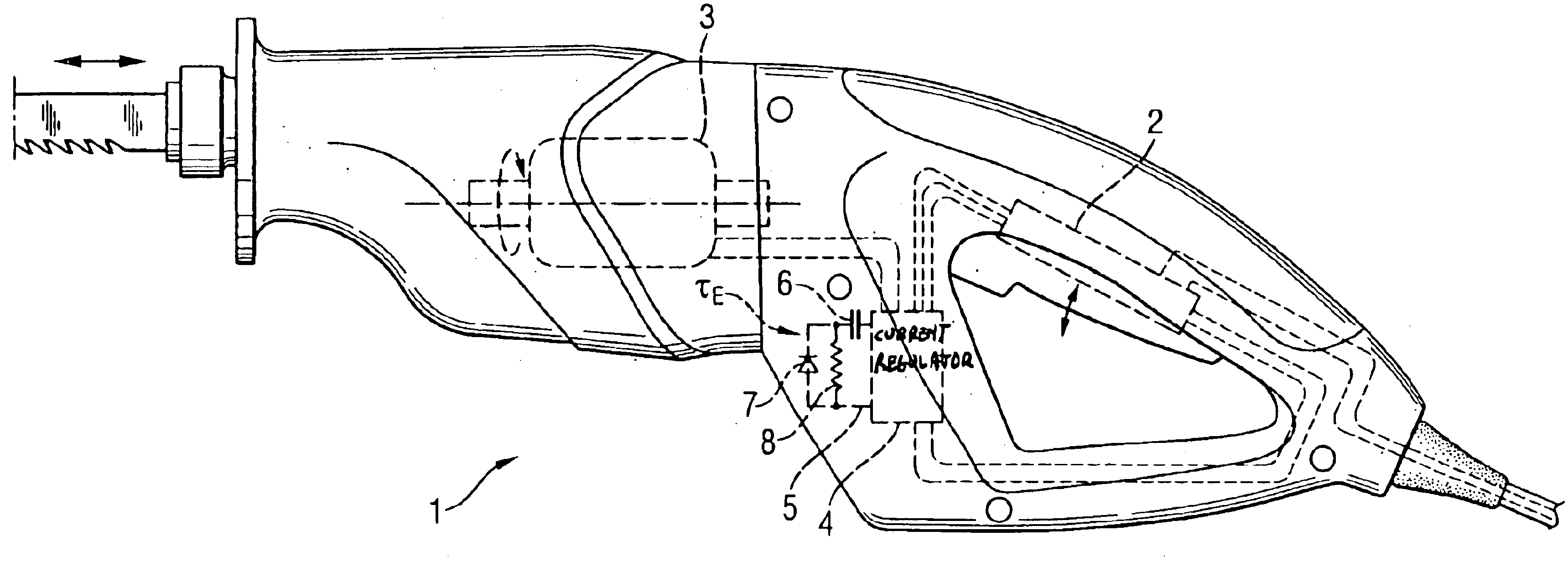
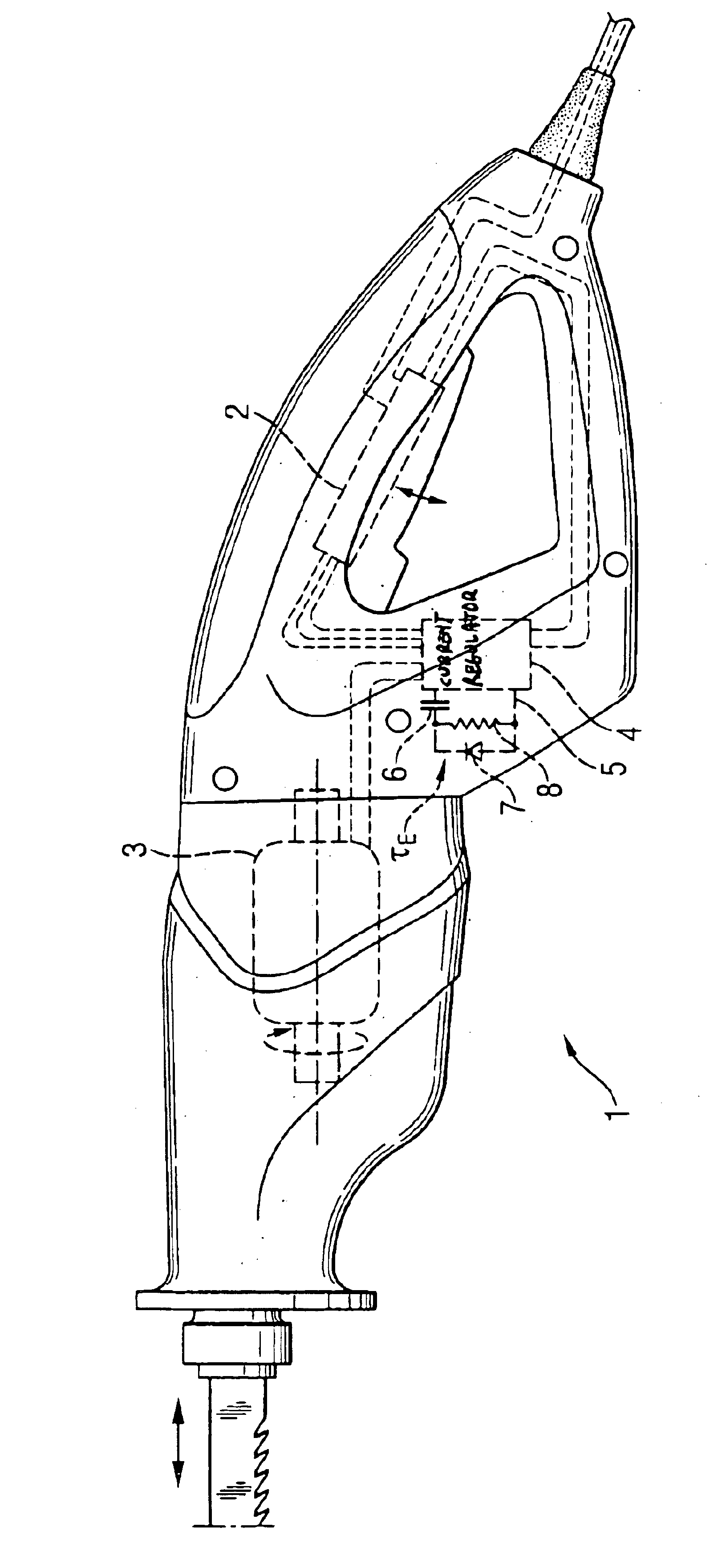
[0011]According to the FIG. 1, an electrical hand tool machine 1 has a motor switch 2 configured as a button and a current regulator 4 having a soft-start input 5, in whose branch current a timing capacitor 6 is disposed, arranged in the current circuit of the electrical motor 3. An element is arranged between the soft-start input 5 and the capacitor 6 in the form of a diode, whose anode is connected to the soft-start input 5 and whose cathode is connected to the capacitor 6. A timing resistor 8 is arranged parallel to the current-direction-dependent element 7. The discharge time constant TE formed by the product of the capacitance C of the timing capacitor 6 and the resistance value R of the resistor 8 is in the range of time of from 0.1 to 1.0 second.


PUM


Abstract

An electrical hand tool machine (1) having a motor switch (2) configured as a button and a current regulator (4) disposed in the current circuit of an electrical motor (3), having a soft-start input (5), in whose branch current a timing capacitor (6) is arranged. A current-direction-dependent element (7) is arranged between the soft-start input (5) and the capacitor (6).

Description

BACKGROUND OF THE INVENTION[0001]The invention relates to an electrical hand tool machine having a current regulator disposed in the current circuit of an electrical motor having a wired soft-start input.[0002]A damped soft-start controlled over approximately 0.5 to 2 seconds up to the desired motor r.p.m. is common in electrical hand tool machines for preventing sudden torque. Some integrated current regulators have a soft-start input for this purpose, which is controlled by the load current of an externally wired capacitor that acts in a timing manner. In electrical hand tool machines with a motor switch configured as a button, gripping by the guiding hand results in unintentional disconnection of the drive and consequently, despite a controlled running tool, resumes soft-start, wherein the desired r.p.m. is unavailable.[0003]According to DE 19609986, a wiring arrangement for controlling an electrical motor of a hand tool machine has a current regulator arranged in the current cir...

Claims


Application Information

Patent Timeline
Patent Type & Authority Patents(United States)
IPC IPC(8): H02P1/18H02P1/42
CPCH02P1/18B25F5/00
Inventor KONIGBAUER, EGON
Owner HILTI ELLSCHAFAT
Why Eureka
Try Eureka