Steering control system and method

a control system and steering control technology, applied in the field of steering control systems and methods, can solve the problems of increasing the labor cost associated with operating the vehicle, difficult calibration, and increasing the weight of the mechanical subsystem of the vehicl

Inactive Publication Date: 2005-04-19
OSHKOSH CORPORATION
View PDF108 Cites 251 Cited by
  • Summary
  • Abstract
  • Description
  • Claims
  • Application Information

AI Technical Summary

Benefits of technology

[0012]In another embodiment, a vehicle having an electronic control system includes a first set of vehicle wheels with a first wheel angle, a second set of vehicle wheels with a second wheel angle, and a plurality of modes for controlling the second wheel angle as a function of the first wheel angle. The plurality of modes include a first mode and a second mode. The electronic control system is configured to receive input to change from a first mode to a second mode, and, in response to the input, the electronic control unit is configured to operate in the first mode until at least one of the sets of vehicle wheels travels through a straight-ahead position at which time the electronic control unit changes to the second mode.
[0013]In another embodiment, a vehicle having an electronic control system includes a first set of vehicle wheels with a variable first wheel angle, a second set of vehicle wheels with a variable second wheel angle, and a lock configured to maintain the second set of vehicle wheels in a locked position. The electronic control system controls the second wheel angle as a function of information pertaining to a first wheel angle. The locked position of the second set of vehicle wheels is input into the electronic control system as a calibration point for a straight-ahead position of the second set of vehicle wheels.
[0014]In another embodiment, a vehicle having an electronic control system includes a first set of vehicle wheels with a variable first wheel angle and a second set of vehicle wheels with a second wheel angle. The electronic control system controls one or both of the first and second wheel angles. The electronic control system is configured to log the position of one or both of the first and second set of vehicle wheel...

Problems solved by technology

Unfortunately, this type of all wheel steering system adds considerable weight and complexity to the mechanical subsystem of the vehicle.
Unfortunately, the use of two operators has a number of disadvantages such as increasing the labor costs associated with operating the vehicle.
Often these systems are difficult to calibrate and require that the operator to get underneath the truck.

Method used


Image

  • Steering control system and method
  • Steering control system and method
  • Steering control system and method

Examples


Embodiment Construction

A. Fire Truck Control System

[0061]1. Architecture of Preferred Fire Truck Control System

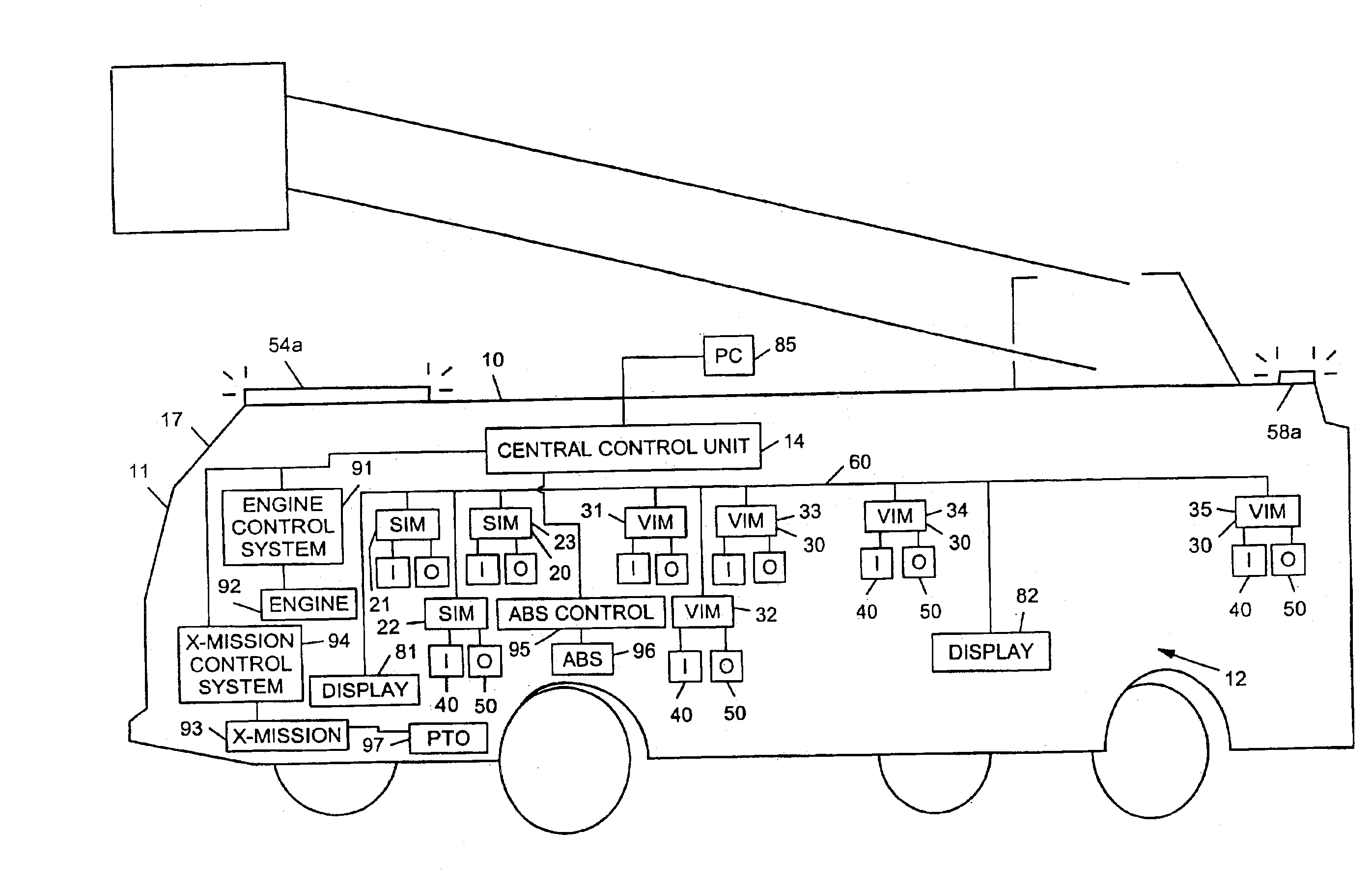
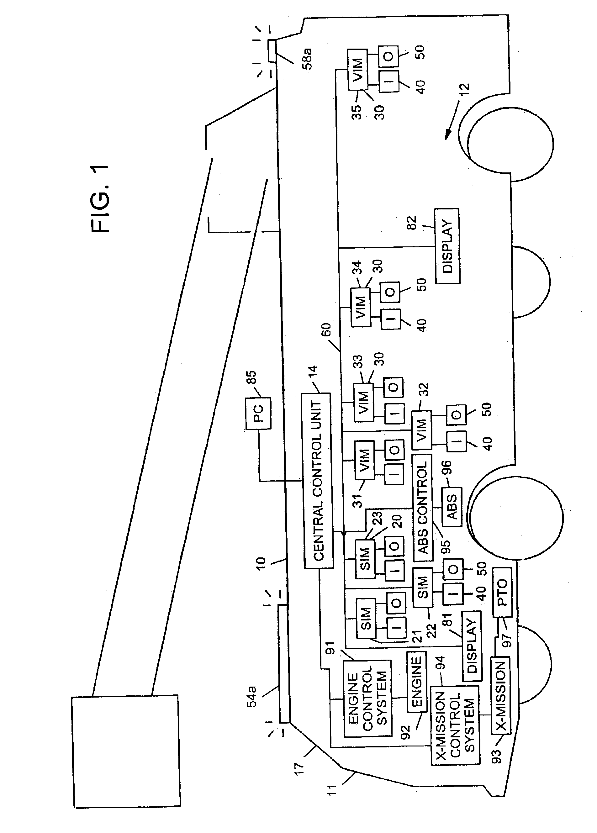
[0062]Referring now to FIG. 1, a preferred embodiment of a fire truck 10 having a control system 12 is illustrated. By way of overview, the control system 12 comprises a central control unit 14, a plurality of microprocessor-based interface modules 20 and 30, a plurality of input devices 40 and a plurality of output devices 50. The central control unit 14 and the interface modules 20 and 30 are connected to each other by a communication network 60.

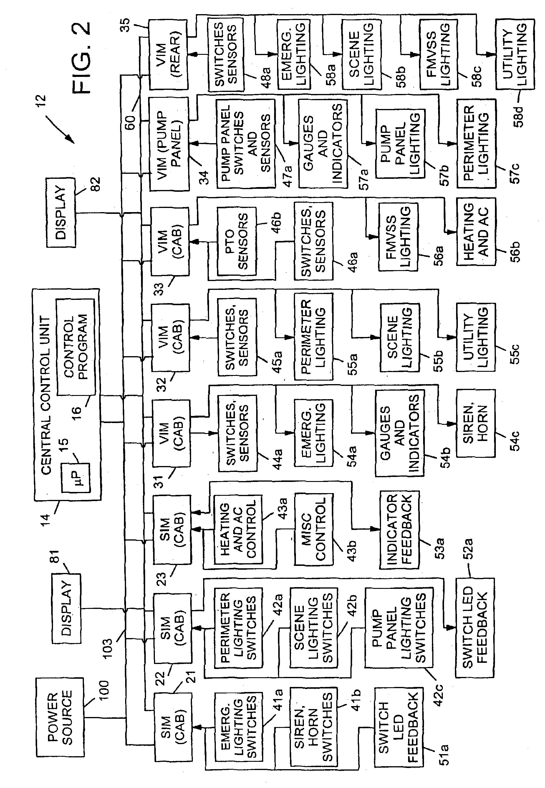
[0063]More specifically, the central control unit 14 is a microprocessor-based device and includes a microprocessor 15 that executes a control program 16 (see FIG. 2) stored in memory of the central control unit 14. In general, the control unit 14 executes the program to collect and store input status information from the input devices 40, and to control the output devices 50 based on the collected status information. The control program may implement a...


PUM


Abstract

An electronic control system for a vehicle includes a plurality of input devices, a plurality of output devices, a communication network, and a plurality of interface modules. The plurality of input devices may include a first input device that provides information pertaining to an angular position of a first vehicle wheel. The plurality of output devices may include an actuator capable of adjusting one or both of the angular position of the first vehicle wheel or an angular position of a second vehicle wheel. The plurality of interface modules can be microprocessor based and can be interconnected to each other by way of the communication network. The plurality of interface modules may also be coupled to the plurality of input devices and to the plurality of output devices. The plurality of interface modules may include one or more interface modules that is coupled to the first input device and to the actuator. The electronic control system can be configured to control the angular position of one or both of the first and second vehicle wheels as a function of the information from the first input device.

Description

CROSS REFERENCE TO RELATED APPLICATIONS[0001]This application claims priority to U.S. Prov. No. 60 / 449,797, filed Feb. 24, 2003, entitled “Steering Control System and Method” and to U.S. Prov. No. 60 / 388,451, filed Jun. 13, 2002, entitled “Control System and Method for an Equipment Service Vehicle,” each of which is hereby expressly incorporated by reference. This application is also a continuation-in-part of U.S. Ser. No. 10 / 325,439, filed Dec. 20, 2002, entitled “Equipment Service Vehicle With Network-Assisted Vehicle Service and Repair,” pending, which (1) is a continuation-in-part of U.S. Ser. No. 09 / 927,946, filed Aug. 10, 2001, entitled “Military Vehicle Having Cooperative Control Network With Distributed I / O Interfacing,” pending, which is a continuation-in-part of U.S. Ser. No. 09 / 384,393, filed Aug. 27, 1999, entitled “Military Vehicle Having Cooperative Control Network With Distributed I / O Interfacing,” now U.S. Pat. No. 6,421,593, which is a continuation-in-part of U.S. S...

Claims


Application Information

Patent Timeline
IPC IPC(8): A62C27/00B60L3/12B60L11/12B60L11/02B60R16/02B65F3/02B65F3/04G07C5/00G07C5/08G08G1/123B60L50/15B60R16/03
CPCA62C27/00B60L3/12B60L11/12B60R16/0315B65F3/043G07C5/08G08G1/20B65F3/045B60L2240/70Y02T90/16G07C5/008Y02T10/7077Y02T10/7291B60L50/15Y02T10/7072Y02T10/72Y02W30/10
Inventor PILLAR, DUANE R.MILLER, JEFFREY J.LINSMEIER, CATHERINE R.MAGNERS, KEVIN W.
Owner OSHKOSH CORPORATION
Why Eureka
Try Eureka