
Closing system for a magneto-rheological damper

a damper and magneto-rheological technology, applied in the direction of shock absorbers, springs/dampers, vibration suppression adjustments, etc., can solve the problems of exhausting lubricant, cumbersome lubricating systems, and adding to the cost of dampers

Inactive Publication Date: 2005-04-26
BWI CO LTD SA +1
View PDF31 Cites 46 Cited by
  • Summary
  • Abstract
  • Description
  • Claims
  • Application Information

AI Technical Summary

Benefits of technology

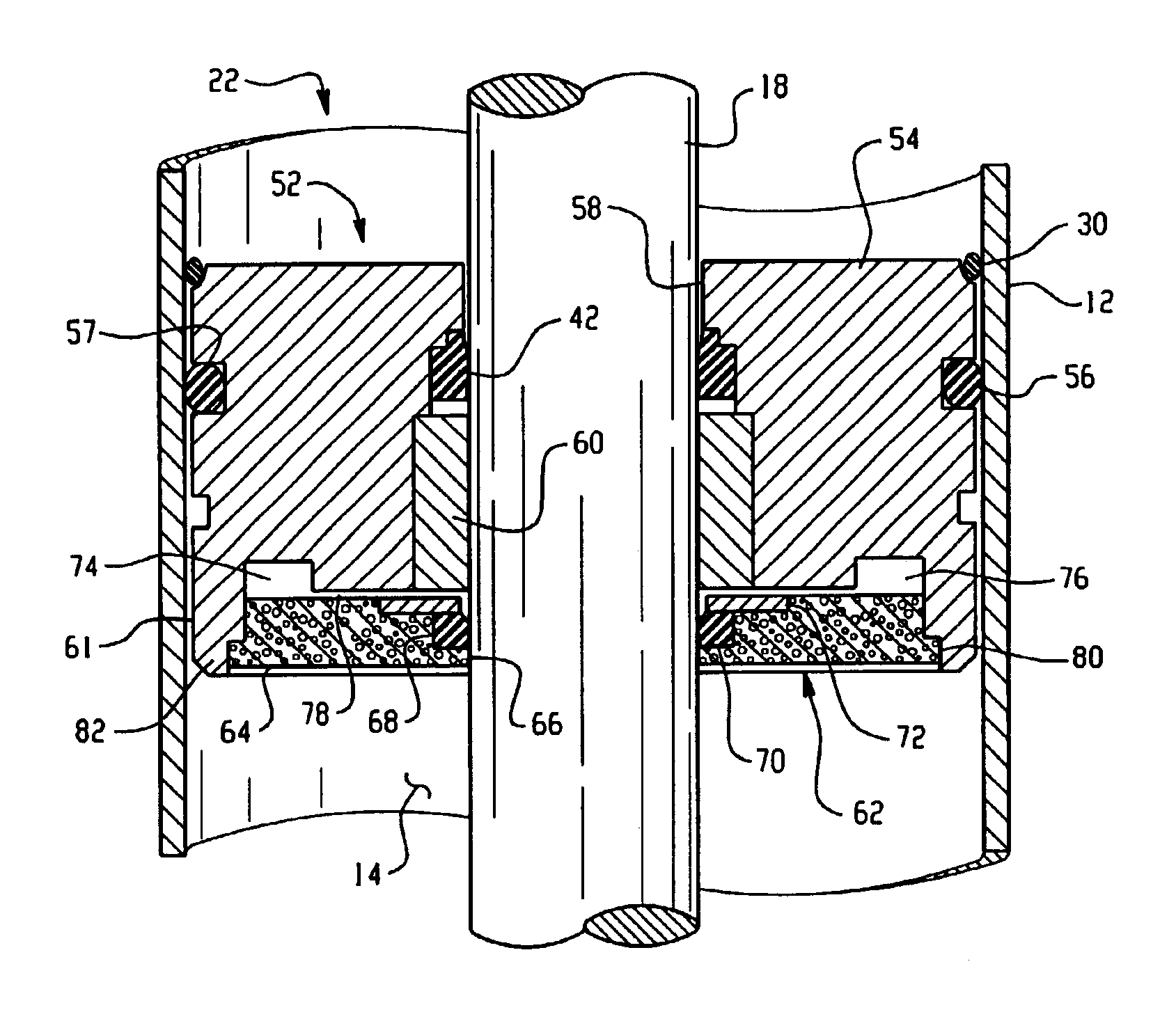
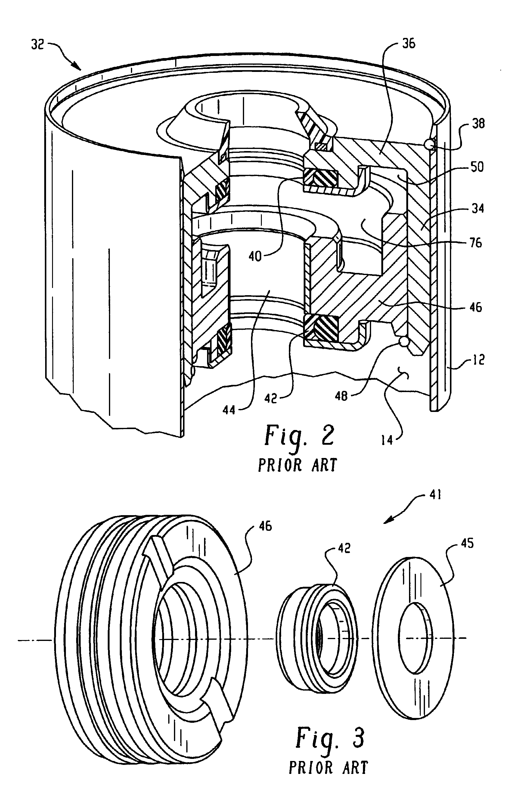
[0006]The present invention is a closing system for use with an MR damper. The closing system provides lubrication for a piston rod without the need for periodic replenishment of the lubricant. According to an embodiment of the present invention, a lubrication chamber and a lubrication passage contain a carrier fluid portion of MR fluid from an adjacent MR fluid reservoir of the damper to lubricate the piston rod guide and piston rod. A seal retainer comprised of a porous material acts as a selective barrier between the MR fluid reservoir and the lubrication chamber, allowing the MR carrier fluid to pass through the porous retainer seal to the lubrication chamber while restraining the micro-particles in the fluid reservoir. The seal retainer thus acts as a filter to segregate the abrasive particles of the MR fluid and allow the MR carrier fluid portion to replenish the lubrication chamber continuously, thereby lubricating the reciprocating piston rod.

Problems solved by technology

Unfortunately, lubricating systems are cumbersome, adding to the cost of the damper.
In addition, the constant motion of the piston rod when the damper is in service will eventually exhaust the lubricant due to limitations inherent in piston rod seals that permit small amounts of lubricant to escape around the piston rod seal.
However, the micro-particles in the MR fluid can have an abrasive effect on the piston rod and piston rod guide as the piston rod moves reciprocally in the piston rod guide.

Method used


Image

  • Closing system for a magneto-rheological damper
  • Closing system for a magneto-rheological damper
  • Closing system for a magneto-rheological damper

Examples


Embodiment Construction

[0014]In the description which follows, like parts are marked throughout the specification and drawings with the same reference numerals. The drawing FIGURES are not necessarily to scale in the interest of clarity and conciseness.

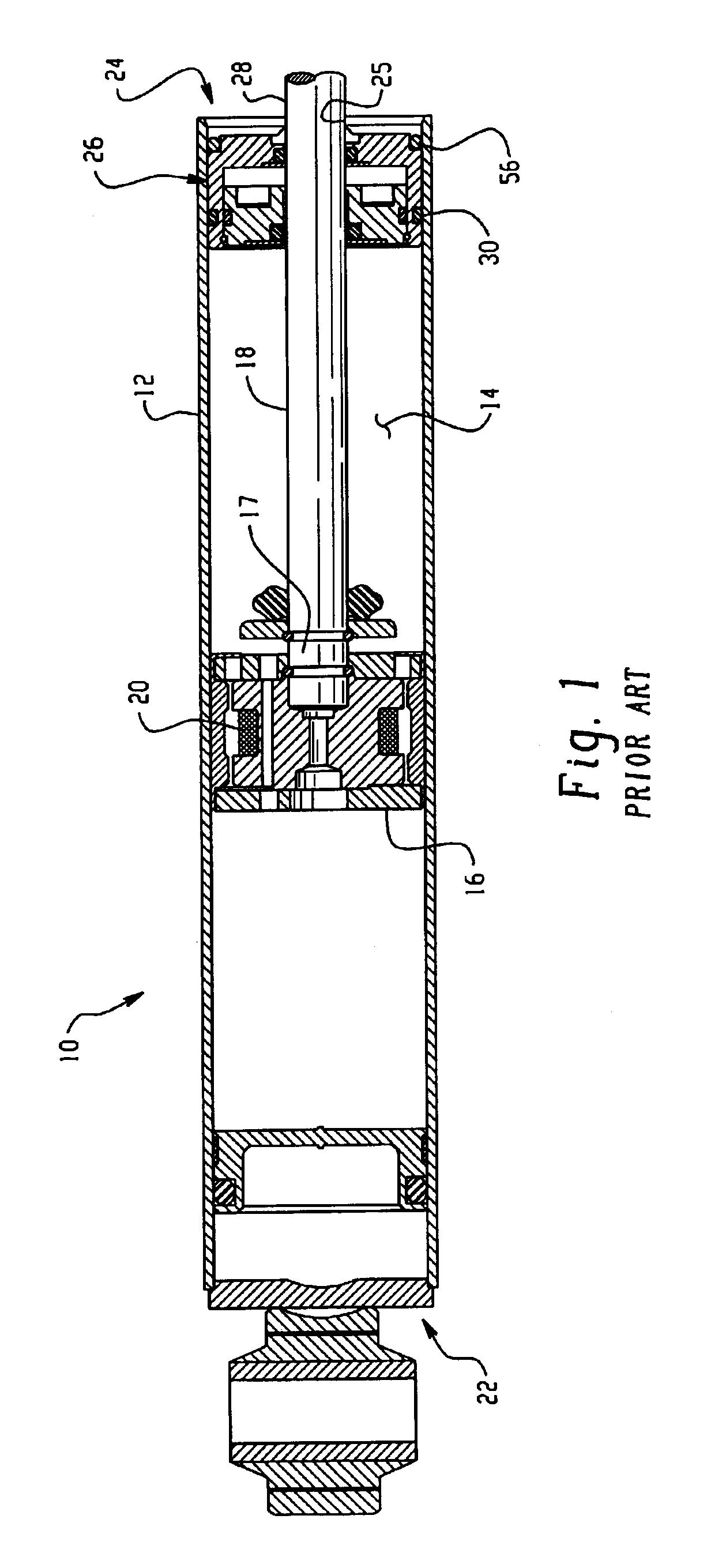
[0015]FIG. 1 illustrates a typical linearly acting MR fluid damper 10. The damper 10 comprises a cylindrical housing 12 having a fluid reservoir 14 adapted to contain MR fluid, a piston 16 slideably moveable within the housing, and a piston rod 18 having a first end 17 attached to the piston. The damper 10 further comprises a magnetic field generating device 20 located within the piston 16. The housing 12 has a first end 22 and a second end 24. The first end 22 of the housing 12 is adapted to be connected to a mounting point, such as a suspension arm. The second end 24 of housing 12 comprises an opening 25 through which a second end 28 of piston rod 18 partially protrudes. The second end 28 of piston rod 18 may be adapted to connect to a vehicle frame. A cl...


PUM


Abstract

A closing system for use with a magneto-rheological (MR) damper. The closing system provides lubrication for a piston rod without a need for periodic replenishment. According to an embodiment of the present invention, a lubrication chamber of the closing system utilizes a carrier fluid portion of MR fluid present in a fluid reservoir of the damper as lubricant for a piston rod guide and the piston rod. A seal retainer comprised of a porous material acts as a selective barrier to the micro-particles in the MR fluid in the fluid reservoir, allowing the MR carrier fluid portion to pass through the porous seal retainer to the lubrication chamber while restraining the micro-particles in the fluid reservoir. The seal retainer thus acts as a filter to segregate the abrasive particles of the MR fluid and allows the MR carrier fluid portion of the MR fluid to continuously replenish the lubrication chamber and lubrication passage to lubricate the piston rod guide and piston rod.

Description

TECHNICAL FIELD[0001]The present invention relates to the field of magneto-rheological (MR) damping devices. In particular, the present invention relates to a closing system for an MR damper.BACKGROUND OF THE INVENTION[0002]Hydraulic dampers are used in many situations where it is desired to isolate sources of vibration or to protect sensitive equipment from shock and vibration. Examples include, but are not limited to, industrial equipment and machinery isolators; industrial robotics; building, bridge and ship isolators; military weapons systems; agricultural equipment; and construction equipment. Hydraulic dampers are also often used as mounts to control movement of vehicle powertrains in response to forces, such as reaction torque and vibration. The mounts also isolate engine vibration from the body of the vehicle.[0003]A well-known type of hydraulic vibration damper is a magneto-rheological (“MR”) damper, which utilizes magneto-rheological (MR) fluids in conjunction with at leas...

Claims


Application Information

Patent Timeline
IPC IPC(8): F16F9/53F16F9/32F16F9/36
CPCF16F9/3242F16F9/535F16F9/362F16F2224/0225
Inventor LUN, SAIMAN
Owner BWI CO LTD SA
Learn More