Aerostat deployment apparatus

a technology for aerostats and deployment apparatuses, which is applied in the direction of mobile visual advertising, instruments, transportation and packaging, etc., can solve the problems of large amount of loose aerostat cloth during inflation, damage to aerostats, and the location of helium inflation “bubbles” to shi

Inactive Publication Date: 2005-04-26
INFORMATION SYST LAB
View PDF10 Cites 18 Cited by
  • Summary
  • Abstract
  • Description
  • Claims
  • Application Information

AI Technical Summary

Benefits of technology

[0014]In this embodiment, an optional restraining line can be used in conjunction with the friction sheet to control the rate of release of aerostat cloth from the container during inflation. The restraining line extends into the aerostat and terminates at an end that is attached to the tail section of the aerostat. The other end of the restraining line is wrapped around an auto-control braking pulley that is preferably mounted on the feed hose. An optional pressure sensor mounted inside the tail section of the aerostat cooperates with the braking pulley to feed-out a restraining line when the pressure inside the aerostat rises above a predetermined amount. On the other hand, the pressure sensor cooperates with the braking pulley to prevent restraining line feed-out when the pressure inside the aerostat falls below a predetermined amount. Thus, the rate of aerostat cloth release can be controlled by the restraining line to maintain the pressure in the inflated portion of the aerostat within a predetermined range.

Problems solved by technology

These procedures inevitably resulted in large amounts of loose aerostat cloth during inflation that can be damaged in even mild wind conditions.
Specifically, the wind can cause the loose aerostat cloth to flap and / or strain, resulting in damage to the aerostat.
Additionally, when loose aerostat cloth is present, the wind can cause the location of the Helium inflation “bubble” to shift.
This shifting of the Helium bubble can also damage the aerostat cloth.
In short, these procedures have generally required a large ground team and have been restricted to optimum weather conditions.

Method used


Image

  • Aerostat deployment apparatus
  • Aerostat deployment apparatus
  • Aerostat deployment apparatus

Examples


Embodiment Construction

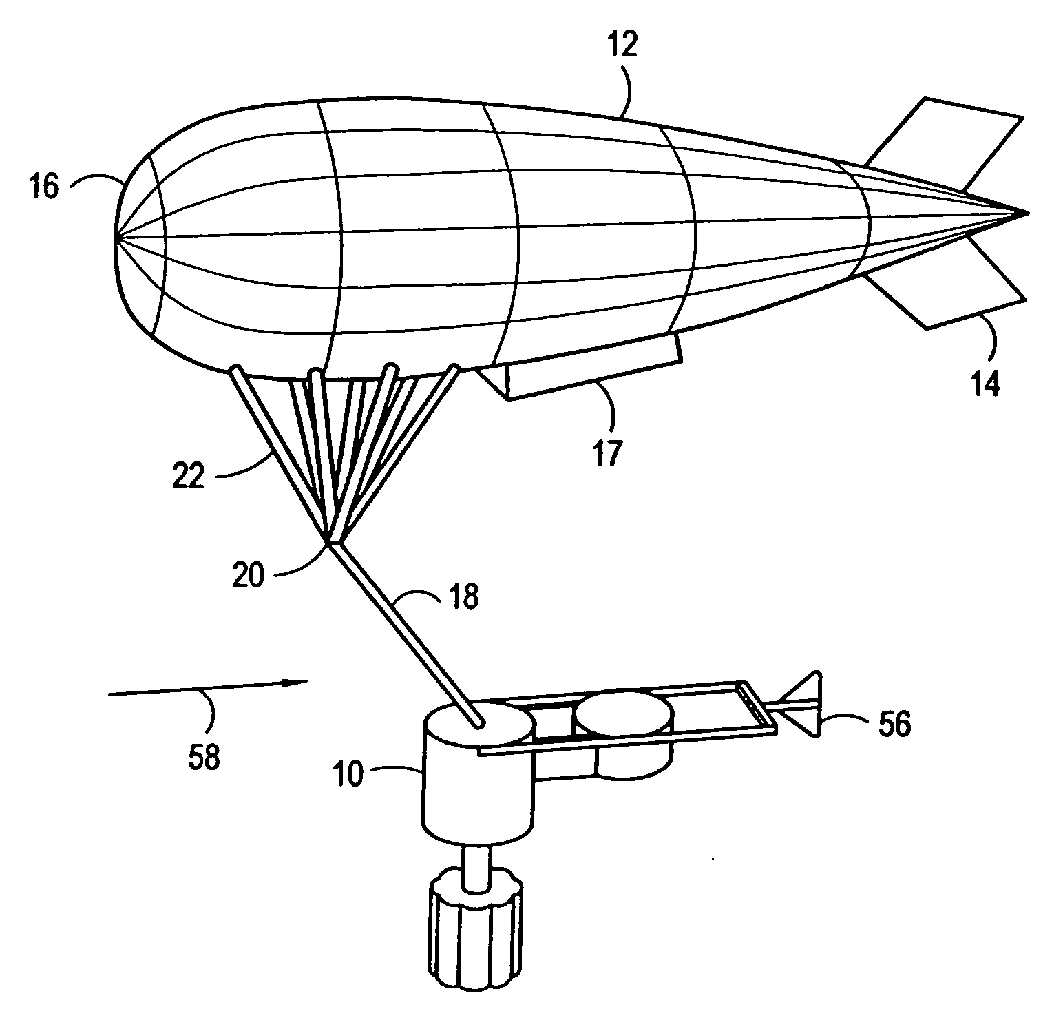
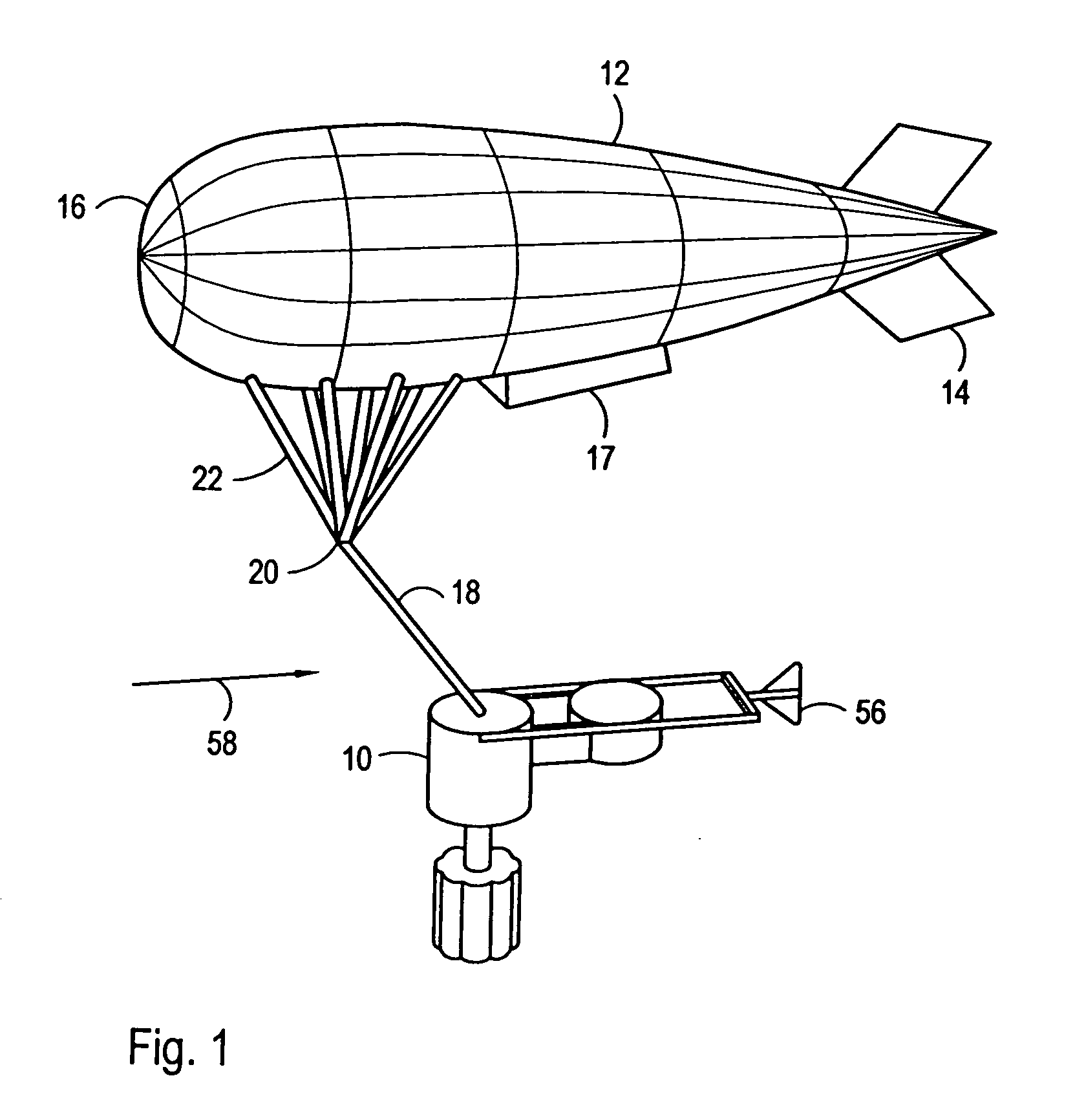
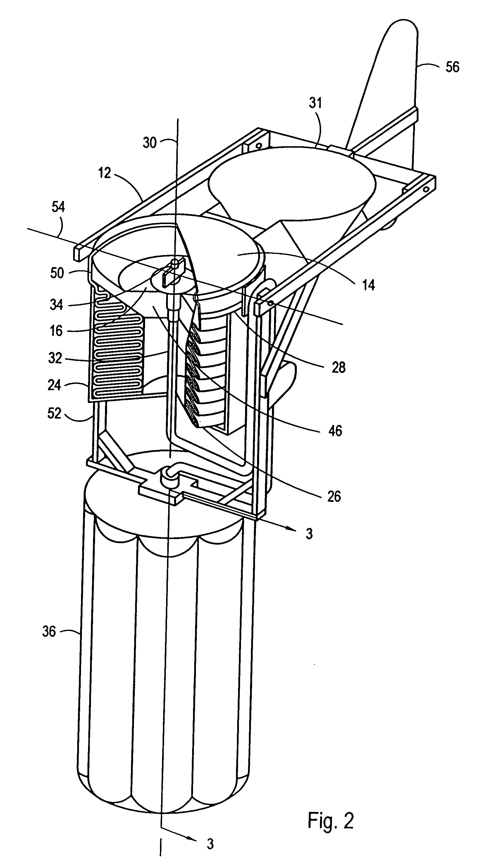
[0006]The present invention is directed to an apparatus for inflating and deploying an aerostat. For the present invention, the aerostat is preferably an elongated cloth balloon having a nose section at one end and a tail section at the other. The inflation and deployment apparatus includes a substantially cylindrical container for housing the deflated aerostat. The cylindrical container is formed with an open end and defines a longitudinal axis. A feed hose is provided to inflate the aerostat. Specifically, the feed hose passes into the container and extends along the longitudinal axis of the container to a hose end that projects slightly from the open end of the container. The other end of the feed hose is connected to a gas source that is located outside the container.

[0007]To position the deflated aerostat on the apparatus, the deflated aerostat is first folded to juxtapose the nose of the aerostat with the tail of the aerostat. Next, the nose of the aerostat is attached to the ...


PUM


Abstract

An apparatus for inflating and deploying an aerostat having a nose section and a tail section includes a cylindrical container for housing the deflated portion of the aerostat. The cylindrical container is formed with an open end and defines a longitudinal axis. A feed hose extends from a gas source, through the container to a hose end that projects axially from the open end of the container. The deflated aerostat is initially folded to juxtapose the nose and tail of the aerostat. Next, the nose of the aerostat is attached to the feed hose end and the remaining portion of the aerostat is folded and inserted into the container. As the tail section is inflated outside of the container, aerostat cloth is drawn from the container. A mechanism is provided to control the release of cloth from the container and maintain pressure in the inflating aerostat within a predetermined range.

Description

[0001]This application is a continuation application of U.S. application Ser. No. 10 / 150,142 filed May 17, 2002 now U.S. Pat. No. 6,715,712, and claims the benefit of U.S. Provisional Application Ser. No. 60 / 291,658 filed May 18, 2001 and U.S. Provisional Application Ser. No. 60 / 336,378 filed Dec. 6, 2001.FIELD OF THE INVENTION[0002]The present invention pertains generally to aerostats and aerostat deployment apparatus. More particularly, the present invention pertains to a compact deployment apparatus that rapidly inflates and deploys an aerostat. The present invention is particularly, but not exclusively, useful as a deployment apparatus that incrementally inflates an aerostat for rapid deployment in windy and otherwise adverse weather conditions.BACKGROUND OF THE INVENTION[0003]Tethered lighter-than-air vehicles provide an ideal platform to elevate various payloads. Typical payloads include sensors, communications antennas and relay equipment, cameras and other devices that can t...

Claims


Application Information

Patent Timeline
Patent Type & Authority Patents(United States)
IPC IPC(8): B64B1/00B64B1/58G09F21/06
CPCG09F21/06B64B1/58
Inventor BOSCHMA, JR., JAMES H.
Owner INFORMATION SYST LAB
Why Eureka
Try Eureka