Adjusting apparatus

a technology of adjusting apparatus and adjusting rod, which is applied in the direction of instruments, television systems, pulse techniques, etc., can solve the problems of achieve the effect of resolving image distortion and unfocus on screen

Inactive Publication Date: 2005-04-26
PURAC BIOCHEM +1
View PDF4 Cites 55 Cited by
  • Summary
  • Abstract
  • Description
  • Claims
  • Application Information

AI Technical Summary

Problems solved by technology

The above-mentioned adjusting apparatus can only provide the horizontal angle adjustment for optical engine, but not provide angle ad

Method used


Image

  • Adjusting apparatus
  • Adjusting apparatus
  • Adjusting apparatus

Examples


first embodiment

[0021]The First Embodiment

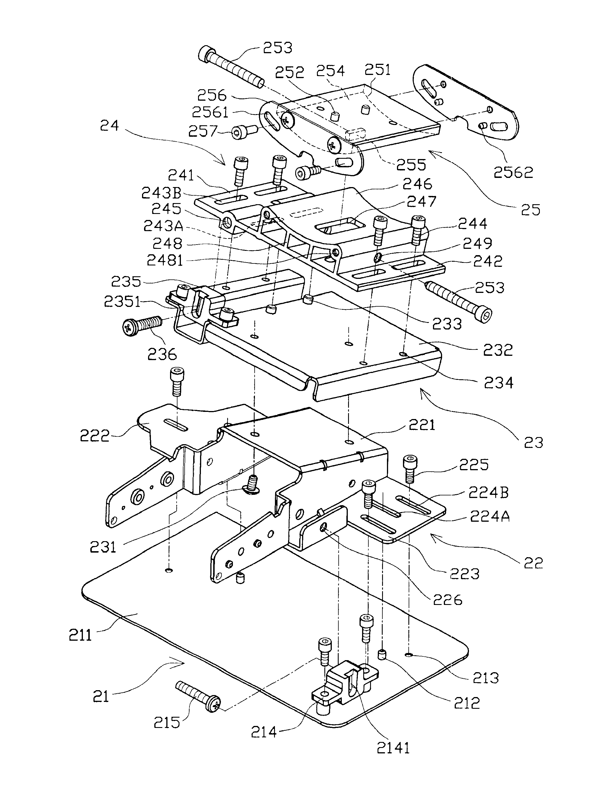
[0022]Referring to FIG. 3 and FIG. 4, an adjusting apparatus 20 of the present invention comprises a base 21, a supporting frame 22, a fixed plate 23, a sliding stand 24, and a carrier 25. The upper surface 251 of the carrier 25 has at least one fixing pin 252 for fixing an optical engine (not shown).

[0023]The base 21 has an upper surface 211. Two edges of the upper surface 211 have a plurality of bulges 212 and fixing openings 213, and one of the edges further has a hold 214. Inside the hold 214 has a receiver 2141. A third adjusting device 215 passes through the hold 214 and has one end clipping into the receiver 2141 of the hold 214.

[0024]The supporting frame 22 is placed on the upper surface 211 of the base 21, and has a top surface 221 which exists an angle of inclination to the base 21. Two edges of the top surface 221 respectively form a left flank 222 and a right flank 223, which form a hat-shape body. The left flank 222 and the right flank 223 have...

second embodiment

[0035]The Second Embodiment

[0036]As shown in FIG. 8 and FIG. 9 that show an adjusting apparatus 30 of the second embodiment of the present invention, the basic structure of the present embodiment is similar to that of the first embodiment. The differences between the present embodiment and the first embodiment are that a top surface 321 of a supporting frame 32 is parallel to a upper surface 311 of a base 31 such that a fixed plate 33, a sliding stand 34, and a carrier 35 having optical engine, sequentially stacking on the supporting frame 32, are still parallel to the base 31. The basic method for adjusting position of optical engine of the present embodiment is the same as the first embodiment. By rotating the first adjusting device 336, the second adjusting device 353, and the third adjusting device 315, the position and inclination angle of optical engine can be quickly adjusted to make image beam, provided by optical engine, precisely project on screen and reach optimum perform...


PUM


Abstract

An adjusting apparatus comprises a base, and a supporting frame, a fixed plate, a sliding stand, and a carrier, which are sequential stacked on the base. An optical engine is fixed on the carrier. By rotating the adjusting device, the axis position of optical engine can be adjusted along sliding slots guided by bulges. By using arc surfaces of the sliding stand and the carrier, the adjusting apparatus clips and pushes the blocks of the carrier to adjust the left and right angle of inclination of optical engine. Therefore, the light beam provided by optical engine could project on a screen precisely and reach the optimum projection performance.

Description

BACKGROUND OF INVENTION[0001]1. Field of the Invention[0002]The present invention relates to an adjusting apparatus, and more particularly to an adjusting apparatus for use in angle or linear adjustment.[0003]2. Description of the Prior Art[0004]Referring to FIG. 1, a rear-projection television of the prior comprises a cover 1 and an optical projection system placed inside the cover 1. The optical projection system comprises an optical engine 2, a small refection mirror 3, a big reflection mirror 4, and a screen 5. An image beam provided by the optical engine 2 impinges onto the small reflection mirror 3 on the front of the optical engine 2, and then onto the big reflection mirror 4 placed on the light path of the reflection beam of the small reflection mirror 3. Finally, the image beam reflected by the big reflection mirror 4 projects on the screen 5 to display an image.[0005]The optical engine 2 provides the image beam whose light path determines if the image of the screen is dist...

Claims


Application Information

Patent Timeline
IPC IPC(8): G03B21/00
CPCG03B21/00G03B21/001
Inventor CHEN, CHUN-YAO
Owner PURAC BIOCHEM
Why Eureka
Try Eureka