Lighting apparatus whose light emitting elements are hard to be taken off

a technology of light emitting elements and light-emitting elements, which is applied in the direction of lighting and heating apparatus, fixed installation, lighting support devices, etc., can solve the problems of difficult material cost, difficult material cost, and the self-emitting of the light-emitting element to be taken off, so as to achieve enhanced rigidity

Inactive Publication Date: 2005-04-26
SATCO PRODS
View PDF1 Cites 23 Cited by
  • Summary
  • Abstract
  • Description
  • Claims
  • Application Information

AI Technical Summary

Benefits of technology

[0011]According to the above structure, rigidity will be enhanced at the element-mounted areas, by reinforcing the areas of the substrate on which light emitting elements are mounted, without accompanied by a weight increase. Therefore i...

Problems solved by technology

This makes the solder to be taken off, which then causes a break between the LED and the wiring pattern, or causes the LED itself to be taken off from the flexible substrate.
However, such a conventional lighting apparatus, having an extra material-thick area on the flexible substrate, is expensive...

Method used


Image

  • Lighting apparatus whose light emitting elements are hard to be taken off
  • Lighting apparatus whose light emitting elements are hard to be taken off
  • Lighting apparatus whose light emitting elements are hard to be taken off

Examples


first embodiment

1. Structure of Lighting Apparatus

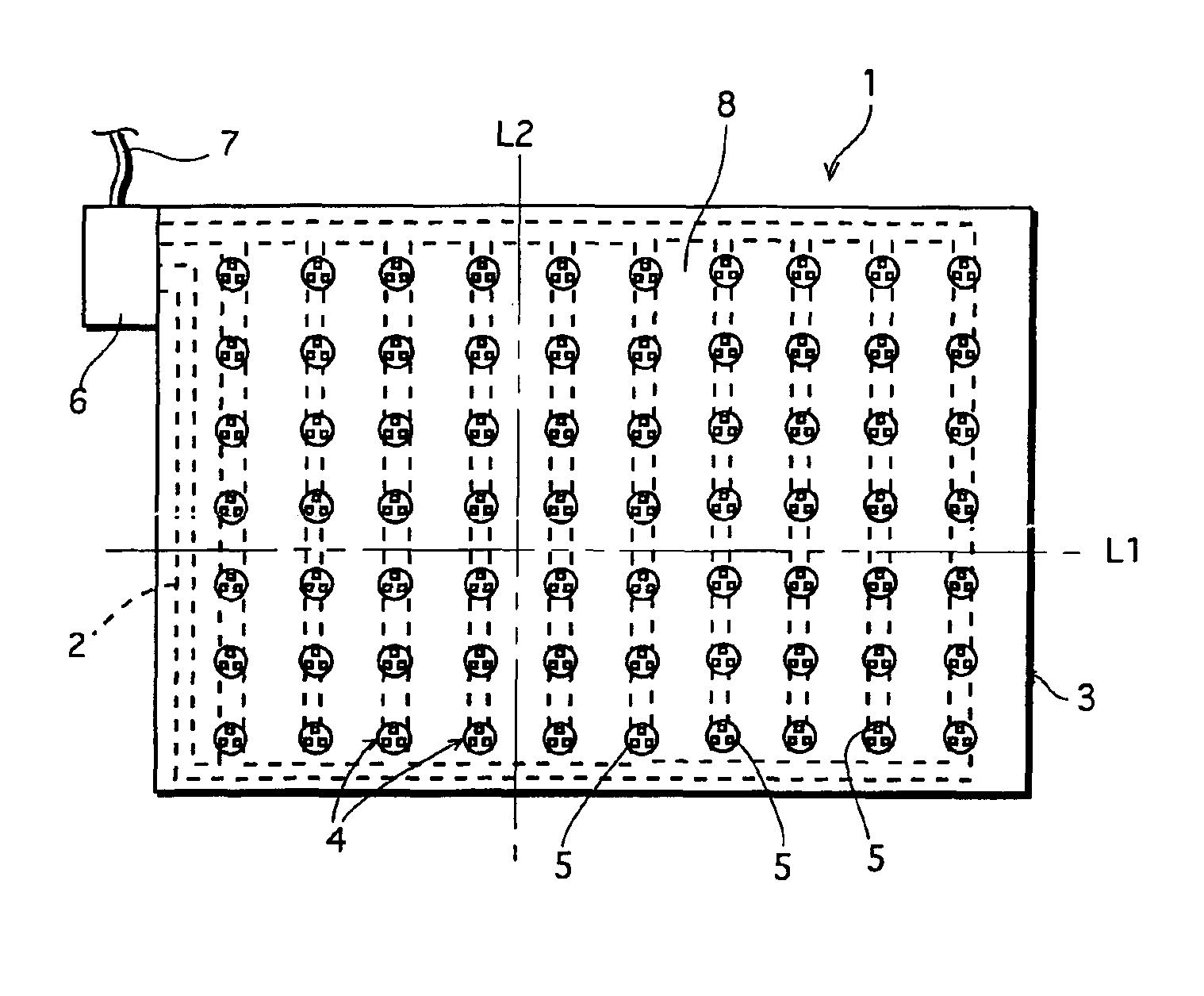
[0026]FIG. 1 is a plan view showing an entire body of the lighting apparatus which relates to the first embodiment of the present invention. The lighting apparatus 1 comprises, as shown in FIG. 1, a substrate 3 having a wiring pattern 2 on the surface, a plurality of LEDs 5 that are arranged on the wiring pattern 2 of the substrate 3, a feeding terminal 6 which is connected to the wiring pattern 2, and a feeding cable 7 for feeding the feeding terminal 6. The feeding path for the plurality of LEDs 5 is: a power source (not shown in figures)→the feeding cable 7→the feeding terminal 6→the wiring patterns 2 through which the light-emission is performed.

[0027]The substrate 3 is a thin plate having substantially rectangular shape, for example, and is formed using a material having flexibility and is deformable, such as a glass epoxy (glass fiber reinforcing plastic). A plurality of areas of the substrate 3 are pressed in the direction of the normal to th...

second embodiment

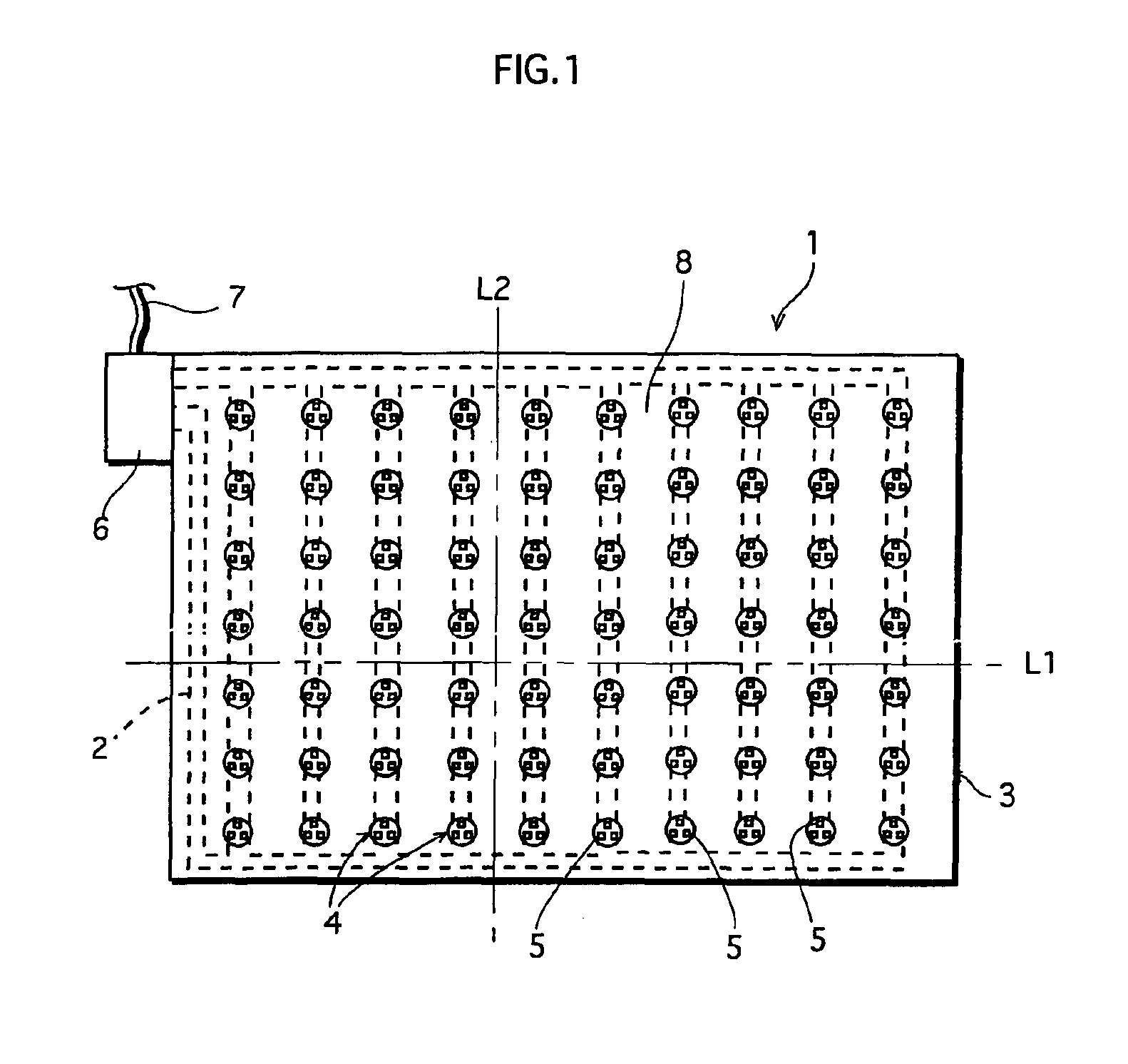
[0049]FIG. 8 is an enlarged sectional view showing the second embodiment of the present invention. In the first embodiment, the concaves are formed, which are concave relative to the substrate 3, by press-forming the substrate 3. In the second embodiment, however, a plurality of convexes 20 are formed, as the element-mounted parts, (see FIG. 8) by press-forming the substrate 3. And on a surface of the convex, LEDs 5R, 5G, and 5B are formed with wiring patterns 2R, 2G, and 2B in-between. Note that the substrate 3, the LEDs 5R, 5G, and 5B, and so on are the same as the ones found in the first embodiment, which will be assigned same respective numbers and will not be detailed in the following description.

[0050]FIG. 9 is an enlarged plan view of the substrate 3. Each convex 20 is formed on a LED 5-mounted surface of the substrate 3, in such a way that the convex 20 bulges out in the direction of the normal to the LED 5-mounted surface. The convexes 20 bulges out substantially in a shape...


PUM


Abstract

In the present invention, a plurality of concaves are provided for one main surface of a flexible substrate by press-forming. Each concave has a flat surface which is substantially parallel to the main surface of the substrate, and mounted on the flat surface are three LEDs each emitting colored light of red, green, and blue respectively.

Description

[0001]This application is based on application No. 2001-284107 filed in Japan, the contents of which are hereby incorporated by reference.BACKGROUND OF THE INVENTION[0002]1. Field of the Invention[0003]The present invention relates to a lighting apparatus on which light emitting elements are mounted, and in particular, to a lighting apparatus that can be bent.[0004]2. Description of Background Art[0005]A light emitting diode (hereinafter simply “LED”) is seen as a candidate for a light source of the next generation since an LED has a compact body, a long life-span, and can be expected to have a high luminous efficiency in the future. One application form of LED is to apply an LED lighting apparatus on a surface of a cylindrical column, for the purpose of using the column as an illumination lamp. It is necessary to bend the lighting apparatus along the surface of the column in order to realize this application.[0006]However, simple soldering of LED on a flexible substrate also bends ...

Claims


Application Information

Patent Timeline
IPC IPC(8): H01L25/075H05K1/18F21V19/00F21S2/00F21S8/04F21Y101/02H01L33/56H01L33/58H01L33/62
CPCH01L25/0753F21Y2101/02H05K1/189Y10S362/80H01L2224/48091H01L2224/48247H01L2224/45144H01L2924/00H01L2224/73265F21Y2115/10H01L2924/00014
Inventor MATSUI, NOBUYUKINAGAI, HIDEOTAMURA, TETSUSHIHATADA, KENZO
Owner SATCO PRODS
Why Eureka
Try Eureka