Main switch conveying apparatus for vacuum circuit breaker

a conveying apparatus and vacuum circuit breaker technology, applied in circuit-breaking switches, circuit-breaking switches for excess currents, switchgear with withdrawable carriages, etc., can solve the problems of increasing the number of parts, complicated assembly process, and inadaptable conventional main switch conveying apparatus for vacuum circuit breaker state-of-art technology

Active Publication Date: 2005-04-26
LG IND SYST CO LTD
View PDF12 Cites 43 Cited by
  • Summary
  • Abstract
  • Description
  • Claims
  • Application Information

AI Technical Summary

Benefits of technology

[0022]Accordingly, the present invention has been made to solve the above-mentioned problems occurring in the prior art, and an object of the present invention is to provide a main switch conveying apparatus for a vacuum breaker including a braking means capable of stopping a main switch at a test position, a safety position, and an operating position. And another object of the present invention is to provide a main switch conveying apparatus for a vacuum breaker including a braking means capable of locking a position of the main switch at above three position to avoid an erroneous operation.

Problems solved by technology

However, the above mentioned main switch conveying apparatus is only adaptable for moving the main switch between two positions, such as the test position and the run position of the vacuum circuit breaker.
Thus, the conventional main switch conveying apparatus is not adaptable for a state-of-art vacuum circuit breaker.
Although it is possible to move the main switch between three positions by modifying the structure of the conventional main switch conveying apparatus, the number of parts is increased, an assembling process thereof is complicated, and a manufacturing cost thereof is increased while lowering a preciseness of an operation.
In addition, since a braking apparatus for stopping and locking the carriage at each of the three positions is not provided, a worker cannot easily recognize the position of the main switch of the vacuum circuit breaker.
Thus, the worker manipulates the main switch conveying apparatus in the reverse direction of his intention, the carriage can be moved to the reverse direction of user's intention, so that risk is high.

Method used


Image

  • Main switch conveying apparatus for vacuum circuit breaker
  • Main switch conveying apparatus for vacuum circuit breaker
  • Main switch conveying apparatus for vacuum circuit breaker

Examples


Embodiment Construction

[0042]Hereinafter, a preferred embodiment of the present invention will be described with reference to the accompanying drawings. In the following description and drawings, the same reference numerals are used to designate the same or similar components, and so repetition of the description on the same or similar components will be omitted.

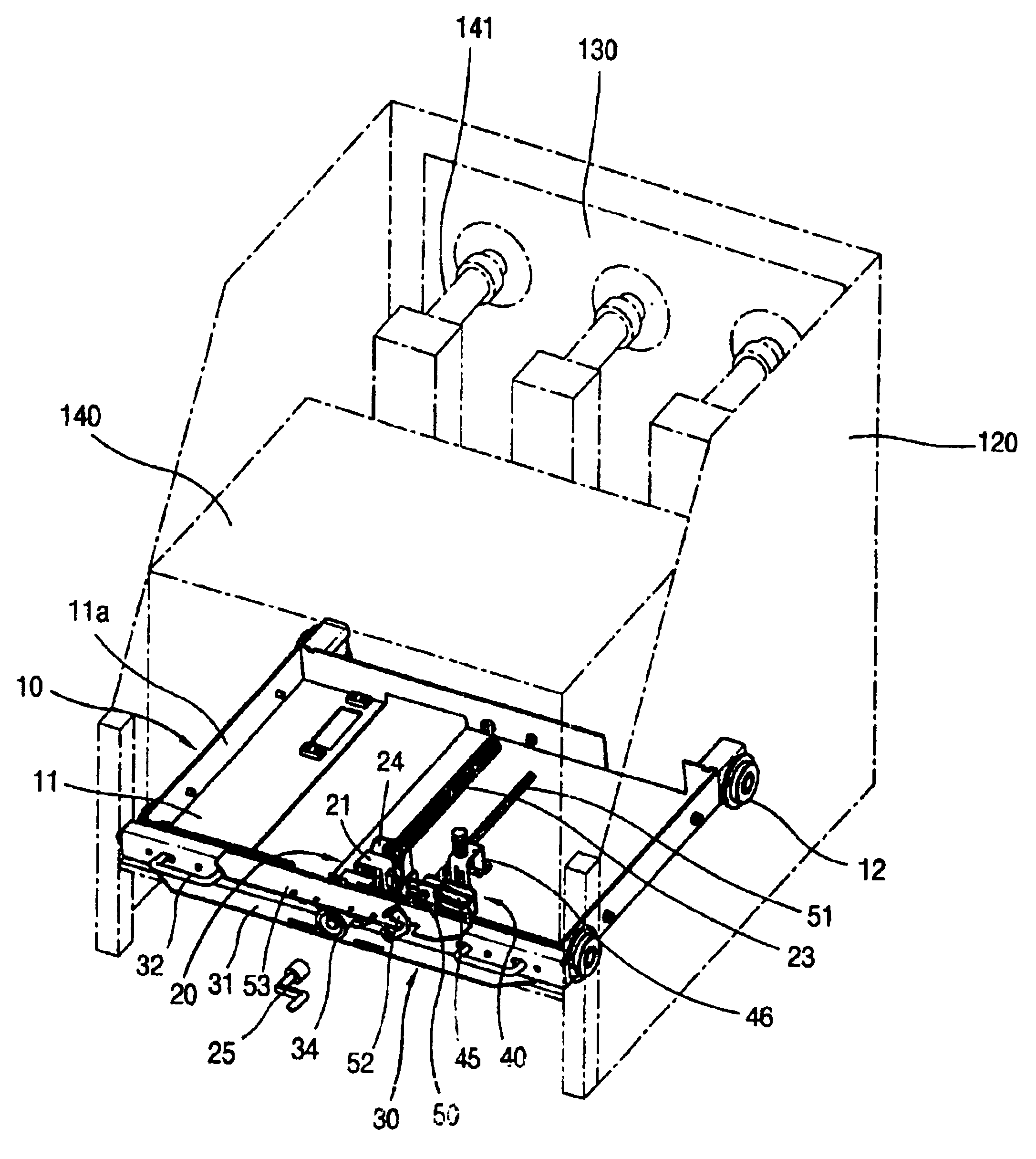
[0043]As shown in the FIG. 7, according to one embodiment of the invention, a vacuum circuit breaker is installed in a cage 120 and the cage 120 has electrical load and source terminals 130 at its rear portion. A main switch conveying apparatus for such breaker comprises a carriage 10 for conveying the main switch 140 loaded on the carriage 10 in such a manner that the main switch 140 is coupled to or separated from the terminals 130; a carriage actuating assembly 20 including a lead screw 23 for providing a driving force to move the carriage 10 and provided with braking recesses at the predetermined positions on the lead screw 23 in such a manner...


PUM


Abstract

Disclosed is a main switch conveying apparatus for a vacuum circuit breaker. The main switch conveying apparatus for a vacuum circuit breaker installed in a cage having electrical load and source terminals, the main switch conveying apparatus includes a carriage for conveying the main switch loaded on the carriage in such a manner that the main switch is coupled to or separated from the terminals, a carriage actuating assembly including a lead screw for providing a driving force to move the carriage and provided with braking recesses at the predetermined positions on the lead screw in such a manner that the carriage is stopped at a test position, a safety position and a run position of the main switch, and a conveying nut fixed on the carriage to mesh with the lead screw and movable together with the carriage relatively to the lead screw, a girder assembly detachably supported on both front sidewalls of the cage for supporting one end of the lead screw to rotate, a brake assembly installed on the carriage for stopping the carriage by locking the lead screw at positions of the braking recesses; and a brake releasing assembly for releasing the locking of the brake assembly. The carriage having the main switch loaded thereon moves along the lead screw, while allowing the main switch to be positioned in the safety, test and run positions of the main switch. The user easily recognizes the position of the main switch. If the main switch conveying apparatus is inversely operated, the movement of the main circuit is stopped so that the main circuit is precisely and rapidly moved.

Description

BACKGROUND OF THE INVENTION[0001]1. Field of the Invention[0002]The present invention relates to a main switch conveying apparatus for a vacuum circuit breaker, and more particularly to a conveying apparatus capable of conveying a main switch of a vacuum circuit breaker in such a manner that the main switch can be coupled / separated to / from an electric load or source terminals installed at a rear position of a cage of the vacuum circuit breaker and can be stopped at a safety position, a test position, and a run position of the vacuum circuit breaker.[0003]2. Description of the Prior Art[0004]As generally known in the art, vacuum circuit breakers are used for protecting circuits and appliances by rapidly breaking circuits simultaneously with quick extinguishing arc, which is generated during an opening / closing operation of such vacuum circuit breakers under a normal load state or when shutting off fault current, in a vacuum container.[0005]Hereinafter, a conventional main switch conve...

Claims


Application Information

Patent Timeline
Patent Type & Authority Patents(United States)
IPC IPC(8): H02B11/00H02B11/133H01H33/66
CPCH02B11/133H01H33/66
Inventor YOON, SEOK-JUNG
Owner LG IND SYST CO LTD
Why Eureka
Try Eureka