Stator coil made of joined conductor segments for rotary electric machinery and method for manufacturing the same

a technology of rotary electric machinery and joined conductors, which is applied in the direction of dynamo-electric machines, electrical apparatus, commutators, etc., can solve the problems of oblique head and end portions, difficult to insert the rotor into the inside, and disadvantages of conventional joined segment stator coils

Inactive Publication Date: 2005-04-26
DENSO CORP
View PDF27 Cites 24 Cited by
  • Summary
  • Abstract
  • Description
  • Claims
  • Application Information

AI Technical Summary

Benefits of technology

[0021]An object of the present invention is to reduce, in a stator coil made of conductor segments which are inserted into slots of a stator core and are joined sequentially, a stress at an insulating coating of a conductor segment.

Problems solved by technology

However, the conventional joined segment stator coil has disadvantages as stated below.
Therefore, the conventional manufacturing process has a disadvantage that the oblique head portions and oblique end portions, particularly those at innermost radial side go beyond the inner circumferential surface of the stator core, thereby making it difficult to insert the rotor into the inside of the stator core and causing an interference of oblique head and end portions with a cooling fan provided on an end surface of the rotor.
Accordingly, the conventional manufacturing process has another disadvantage that a great stress is generated in the insulating coating at the border portion, thereby degrading an insulation of the segment.
This may be a possible disadvantage, when the conventional joined segment stator coil is to be applied for a high voltage rotary machinery such as a vehicle motor.

Method used


Image

  • Stator coil made of joined conductor segments for rotary electric machinery and method for manufacturing the same
  • Stator coil made of joined conductor segments for rotary electric machinery and method for manufacturing the same
  • Stator coil made of joined conductor segments for rotary electric machinery and method for manufacturing the same

Examples


Embodiment Construction

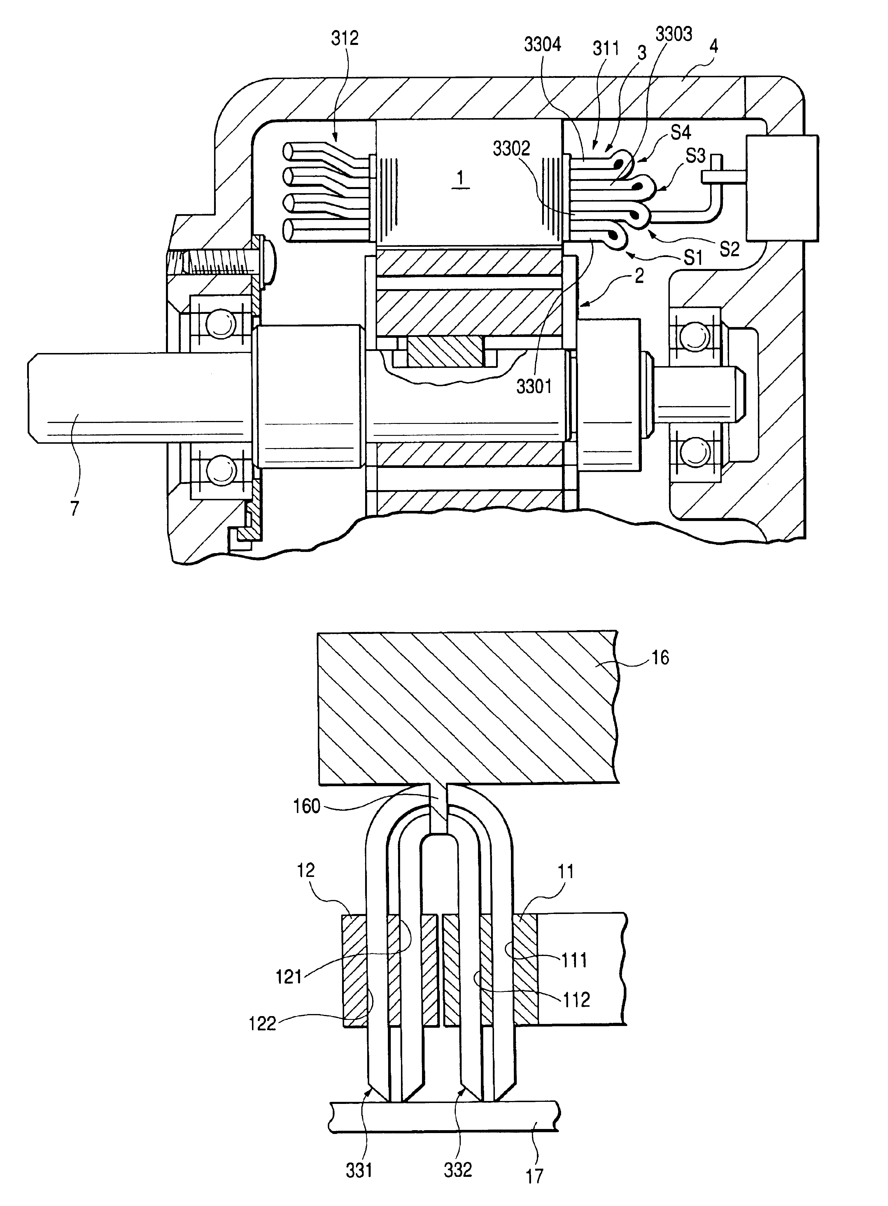
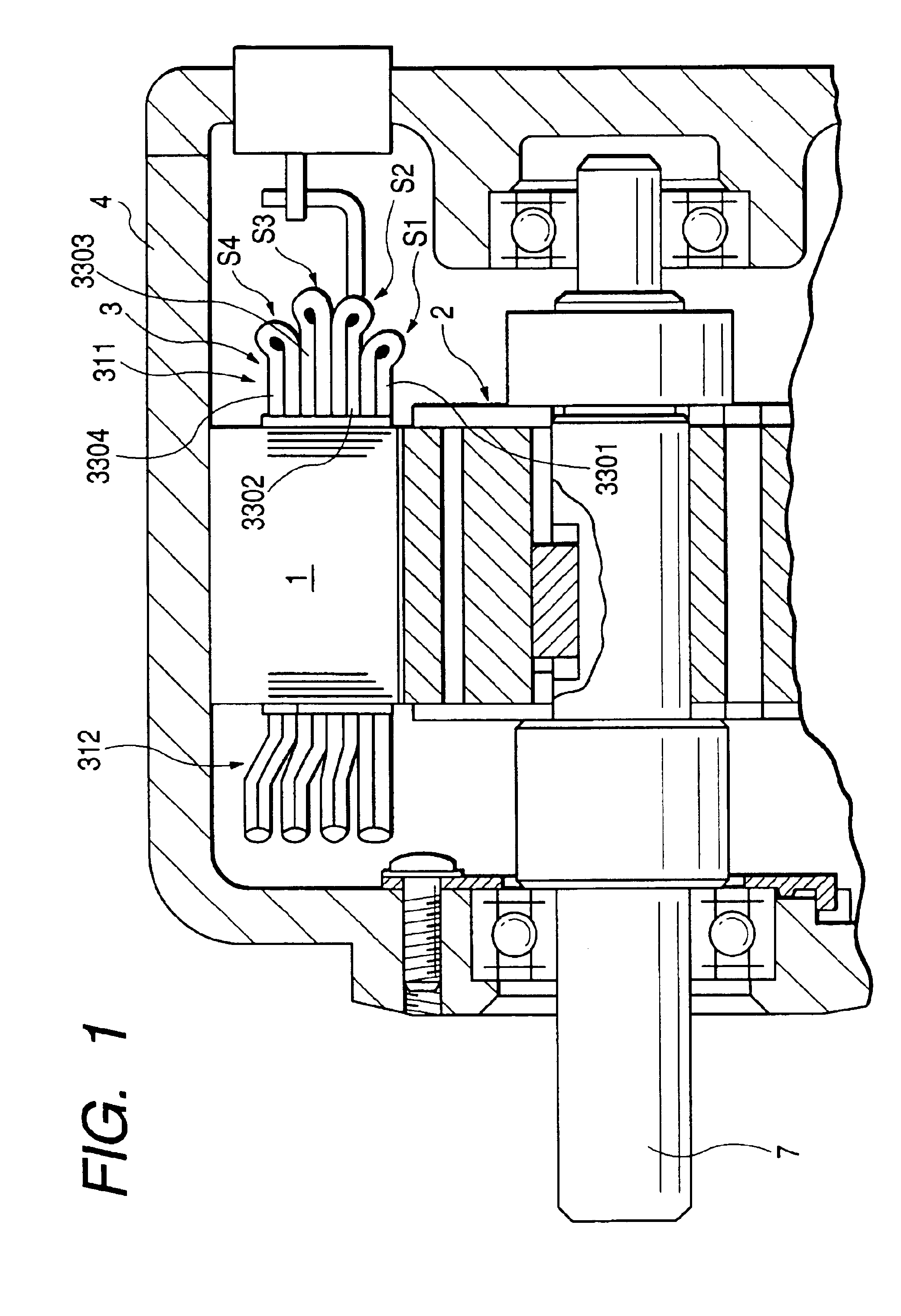
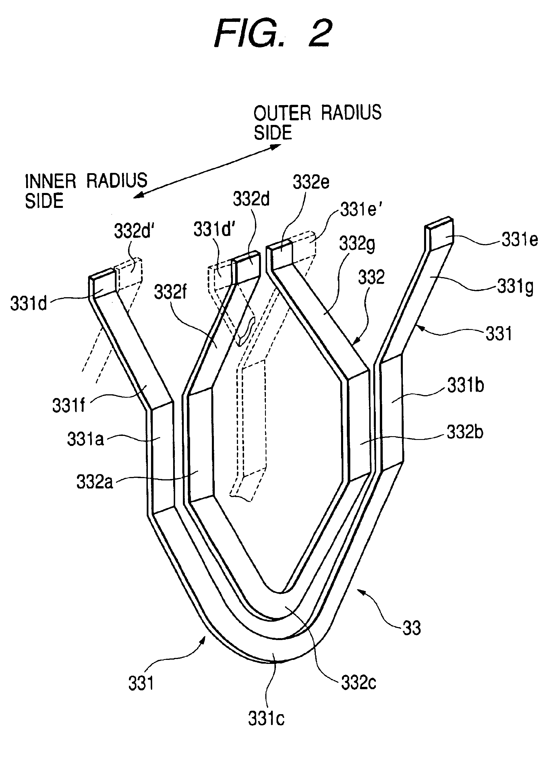
[0077]A preferred embodiment of the present invention is explained, referring to the drawings. FIG. 1 is a cross sectional view along the axial direction of the rotary machinery for a motor employing the stator coil of the present invention for driving an automotive vehicle, wherein coil end portion of the stator coil is schematically illustrated. FIG. 2 is a perspective view of a conductor segment set. FIG. 3 is a partial cross sectional view of segments received in the slots of the stator core.

Driving Motor

[0078]As shown in FIG. 1, the driving motor comprises a stator core 1, a rotor 2, a stator coil 3, a hausing 4 and a rotating axis 7. The stator core 1 is fixed at an inner wall of the hausing 4, while the stator coil 3 is wound through the slots of the stator core 1. The rotor 2 is an IPM rotor fixed with the rotating axis 7 rotatably supported by the hausing 4, and is disposed inside the stator core 1. The stator coil 3 is a three phase armature winding coil which is fed by a ...


PUM


Abstract

A stator coil has a plurality of segments serially connected with each other to construct one turn in a phase coil. Each of the segments has a pair of slot conductor portions, a head portion which is projected toward an end of the stator core, and a pair of projected end portions which project from another end of the stator core. The head portion has head tip portion, a pair of head oblique portions, and a pair of projected end portions, each of which is stretched obliquely along the circumferential and axial directions of the stator core. A pair of end tip portions, formed at a tip of the corresponding end oblique portion, is joined with an end tip of the other end tip portion. The head oblique portions or the end oblique portions are made circular-arch-shaped around an axis of said stator core.

Description

BACKGROUND OF THE INVENTION[0001]1. Field of the Invention[0002]The present invention relates to a stator coil constructed by joined conductor segments for rotary electric machines and a method for manufacturing the same.[0003]2. Description of the Related Art[0004]There have been disclosed joined conductor segment stator coils, wherein a plurality of conductor segments inserted into slots of a stator core are sequentially connected one by one. For example, a method for manufacturing the joined conductor coil (joined conductor segment stator coil) by utilizing nearly U-shaped conductor segment in JP No. 3118837.[0005]In JP No. 3118837, legs of a pair of the nearly U-shaped conductor segments are inserted into an entrance of, and are projected from the opposite exits of, a pair of slots distant from each other by a magnet pole pitch of a rotor. Then, the projected legs are bent toward the circumferential direction of the rotor and are sequentially joined together.[0006]Therefore, the...

Claims


Application Information

Patent Timeline
Patent Type & Authority Patents(United States)
IPC IPC(8): H02K3/12H02K15/04H02K3/04
CPCH02K3/12H02K15/064H02K15/0428H02K15/0414
Inventor GOROHATA, TETSUYAKAMAKURA, YOUICHIHIRANO, HITOSHI
Owner DENSO CORP
Why Eureka
Try Eureka