Fixed frequency hysteretic regulator

a hysteretic regulator and fixed frequency technology, applied in process control, amplifiers, instruments, etc., can solve problems such as unworkable designs, difficult curing stability problems, and no control scheme retains all the advantages, and achieves fast response and inherent stability

Inactive Publication Date: 2005-04-26
INFINEON TECH AMERICAS CORP
View PDF12 Cites 29 Cited by
  • Summary
  • Abstract
  • Description
  • Claims
  • Application Information

AI Technical Summary

Benefits of technology

[0017]Fixed Frequency Hysteretic Regulator—The invention provides the fast response and inherent stability of the hysteretic regulator along with the fixed frequency characteristic of the pulse width modulator, while eliminating the main disadvantages of both regulators—the variable frequency of the hysteretic regulator and the compensation network required for stability of the PWM. The result can be called a Fixed Frequency Hysteretic Regulator (FFHR).

Problems solved by technology

To date no control scheme retains all the advantages of all the popular methods, while eliminating the disadvantages, of these methods.
Curing stability problems can be quite challenging, and the inability to solve the compensation network correctly has caused many otherwise good designs to become unworkable.
However, due to the nature of how output voltage ripple is determined and to the dependence of this ripple on the relative magnitudes of the input and output voltages, the frequency of operation of the hysteretic regulator must change with input voltage.
This is the most significant drawback of the hysteretic regulator, since input filtering must be determined based on the lowest frequency of operation, corresponding to the lowest Vin.
The input filter requires physically larger components with decreasing Vin, and the filter becomes wasted space and cost at higher Vin.
Some claim to have observed circuit subharmonic oscillations with hysteretic regulators, causing noise and interference with sensitive control signals.
Most importantly, the response time of the control circuit is compromised in that it must be slowed down to prevent circuit instabilities.
As mentioned above, the required circuitry can be challenging.
Without slowing down the response, wild oscillations of the output voltage can result, and the output may never become stable.
Analog Devices has a method of correcting for variances in ESR, but this method does not compensate for changes in Vin.

Method used


Image

  • Fixed frequency hysteretic regulator
  • Fixed frequency hysteretic regulator
  • Fixed frequency hysteretic regulator

Examples


Embodiment Construction

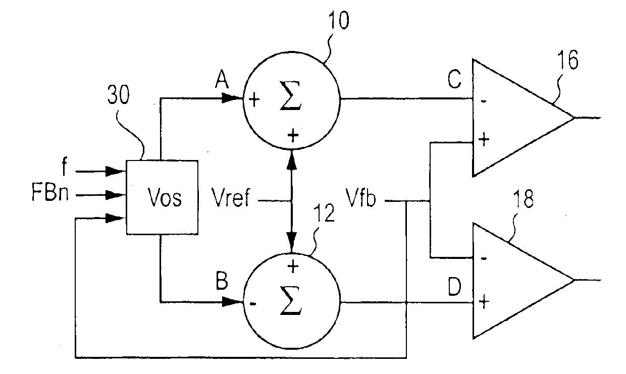
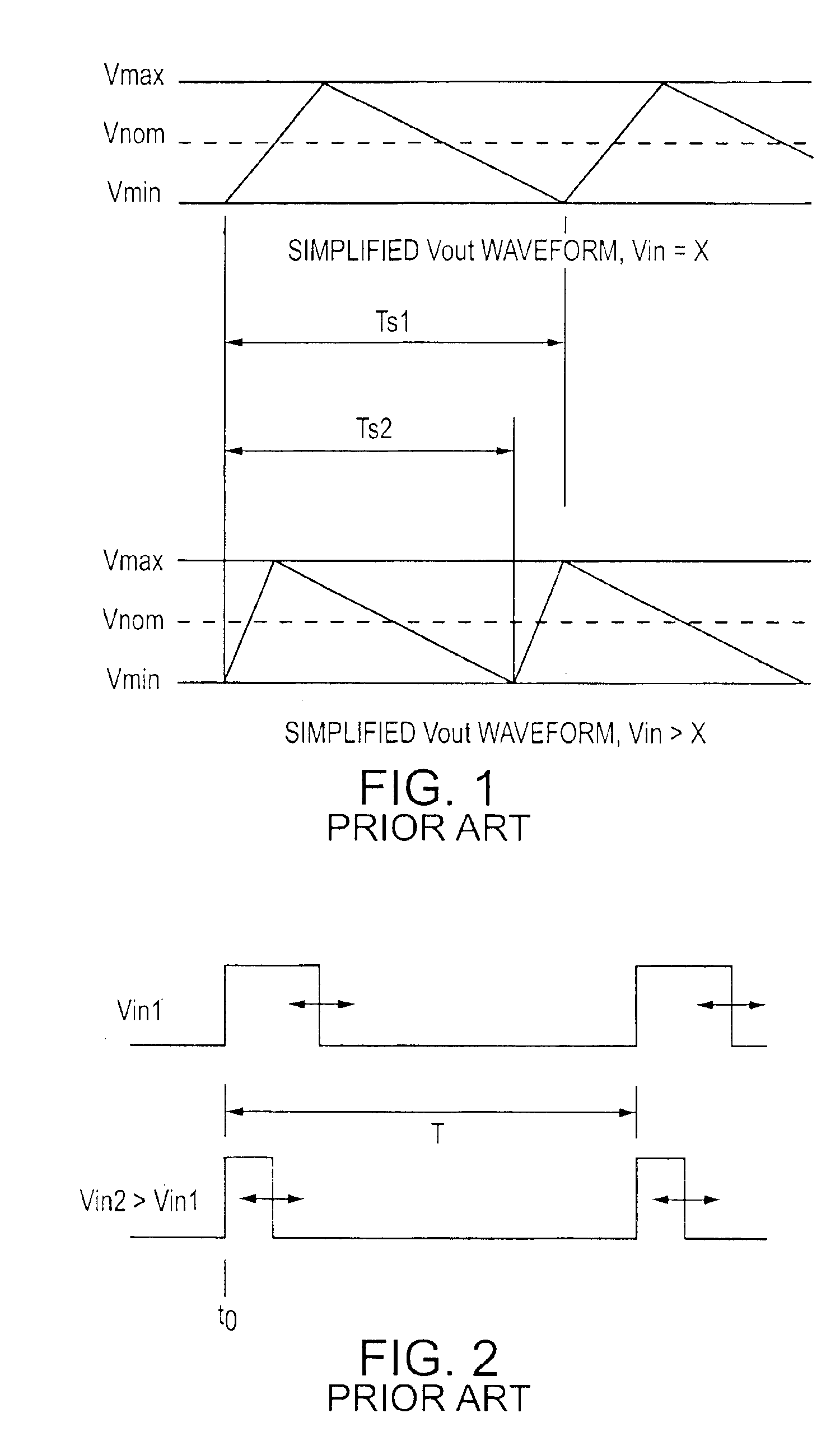
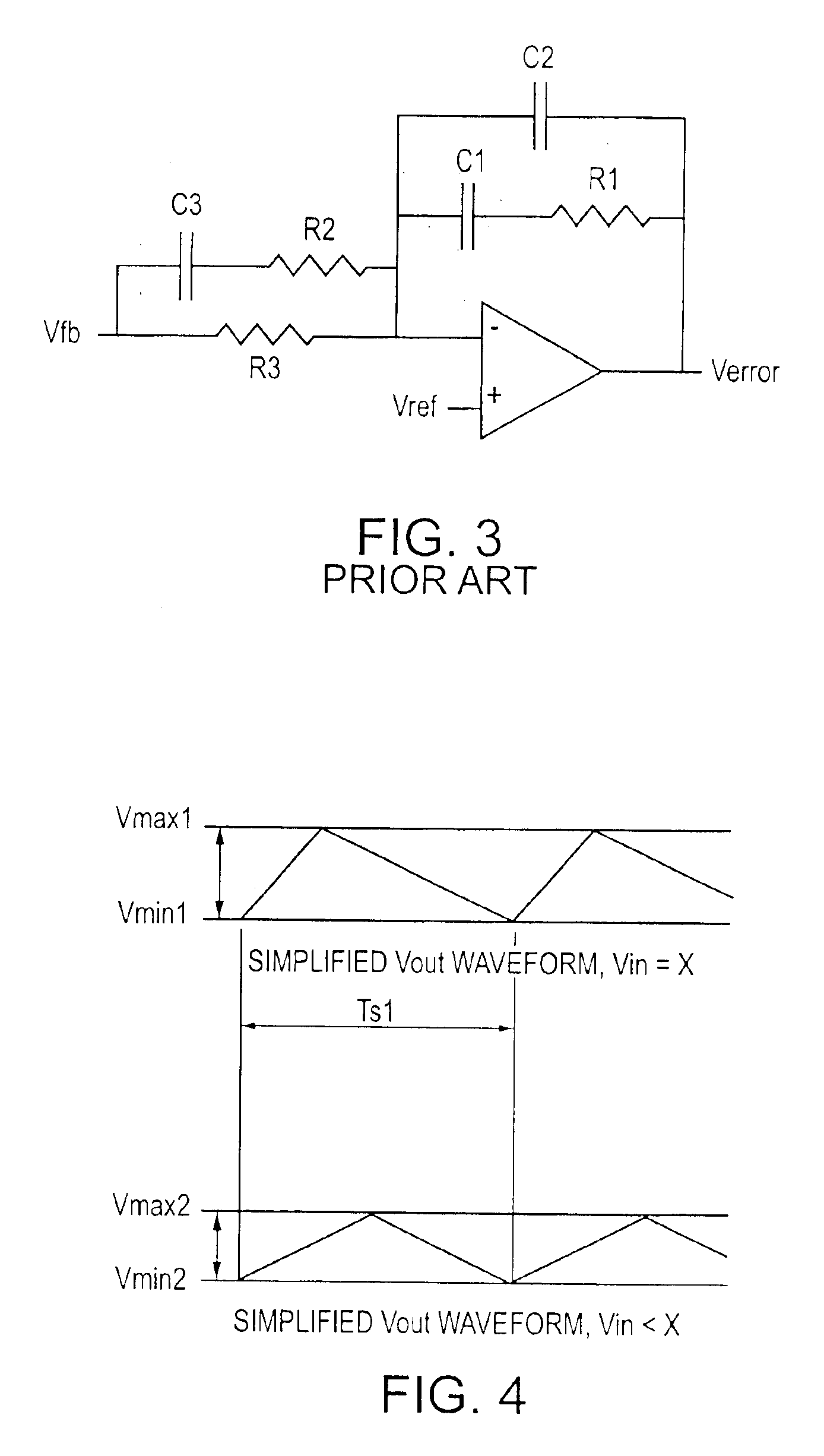
[0032]The characteristics of the FFHR can be accomplished by any number of circuit solutions. According to one aspect of the invention, a hysteretic regulator may have a means of actively varying the window height depending upon circuit conditions. The window will be centered about some portion (depending on the reference voltage of the feedback comparator) of the desired dc output level as in a standard hysteretic regulator. However, instead of the control loop varying the pulse width (horizontal direction, or time base) as in the PWM regulator, the window voltage Vmax−Vmin will be varied (vertical direction, or ripple voltage value). The maximum window variation can be established based on specifications and circuit parameters, including an absolute maximum window voltage specification and a minimum output capacitance ESR. These specifications may be realized in the circuit straightforwardly with a few passive components such as low power resistors. The output falls within certain...


PUM


Abstract

A control circuit for controlling a hysteretic regulator to operate at substantially fixed frequency has a voltage offset circuit which receives a first feedback signal and generates a pair of upper and lower offset voltages; a control reference stage which receives a reference voltage and the upper and lower offset voltages and outputs upper and lower control reference voltages; and a window comparator which receives the upper and lower control reference voltages and an output voltage feedback signal and outputs a pair of upper and lower control voltages for controlling switching of the hysteretic regulator at a fixed frequency. The first feedback signal may be representative of a switching frequency, a temperature or an output voltage of the hysteretic regulator, for example. The voltage offset circuit may further receive a second and / or an additional feedback signal. The first, second and / or additional feedback signals further may be weighted. According to particularly useful embodiments of the invention, the control method for a hysteretic regulator may use both output voltage and switching frequency as primary feedback signals, thereby allowing the window limits (control voltages) to be positioned completely independently and in any possible configuration about the nominal voltage. In other words, the two window limits can be positioned symmetrically or asymmetrically about the nominal voltage, and at the same time the lower window limit can be positioned either below, above, or equal to the upper window limit.

Description

CROSS-REFERENCE TO RELATED APPLICATION[0001]This application is based upon and claims priority of the applicant's U.S. Provisional Application Ser. No. 60 / 421,453 filed Oct. 25, 2002, incorporated by reference.BACKGROUND OF THE INVENTION[0002]1. Field of the Invention[0003]The invention relates to high frequency switching power supplies, and more particularly to a hysteretic regulator adapted for maintaining a constant switching frequency in a switching power supply.[0004]2. Background Art[0005]High frequency switching power supplies are controlled or regulated by several different control schemes. The advantages of some methods are the disadvantages of others, and vice versa. To date no control scheme retains all the advantages of all the popular methods, while eliminating the disadvantages, of these methods. Desirable attributes of a switching regulator include immediate response, inherent power supply stability, and fixed frequency. There is a need for an improved regulator provi...

Claims


Application Information

Patent Timeline
Patent Type & Authority Patents(United States)
IPC IPC(8): G05F1/40G05F1/10
CPCG05F1/40H03F2200/351
Inventor MIHALKA, ALEX
Owner INFINEON TECH AMERICAS CORP
Why Eureka
Try Eureka