Piezoelectric actuator, time piece, and portable device

a technology of electric actuator and timepiece, applied in the direction of electric winding, instruments, horology, etc., can solve the problems of reducing efficiency, increasing the size of the apparatus, and difficulty in stably transmitting the driving force to the rotor

Inactive Publication Date: 2005-04-26
SEIKO EPSON CORP
View PDF34 Cites 29 Cited by
  • Summary
  • Abstract
  • Description
  • Claims
  • Application Information

AI Technical Summary

Problems solved by technology

When the amplification mechanism is used, however, energy is consumed to operate the amplification mechanism, efficiency is lowered, and the size of an apparatus increases.
In addition, when the amplification mechanism is used, it may be difficult to stably transmit a driving force to the rotor.
However, since the stepping motor is constructed by incorporating parts, such as a coil and a rotor, thereinto in an out-of-plane direction, the reduction in thickness of the calendar display mechanism is limited.
For this reason, there is a problem in that the conventional calendar mechanism using the stepping motor is not structurally suited for reducing the thickness.
However, it is difficult for an electromagnetic stepping motor to achieve a reduction in thickness to such an extent that the calendar mechanism can be constructed on the side of the dial.
Therefore, it is necessary for a conventional timepiece to be manufactured by separately designing watch-hand-driving mechanical systems according to whether there is a display mechanism, and this becomes a problem when improving the productivity thereof.

Method used


Image

  • Piezoelectric actuator, time piece, and portable device
  • Piezoelectric actuator, time piece, and portable device
  • Piezoelectric actuator, time piece, and portable device

Examples


first embodiment

A. First Embodiment

A-1. Overall Construction

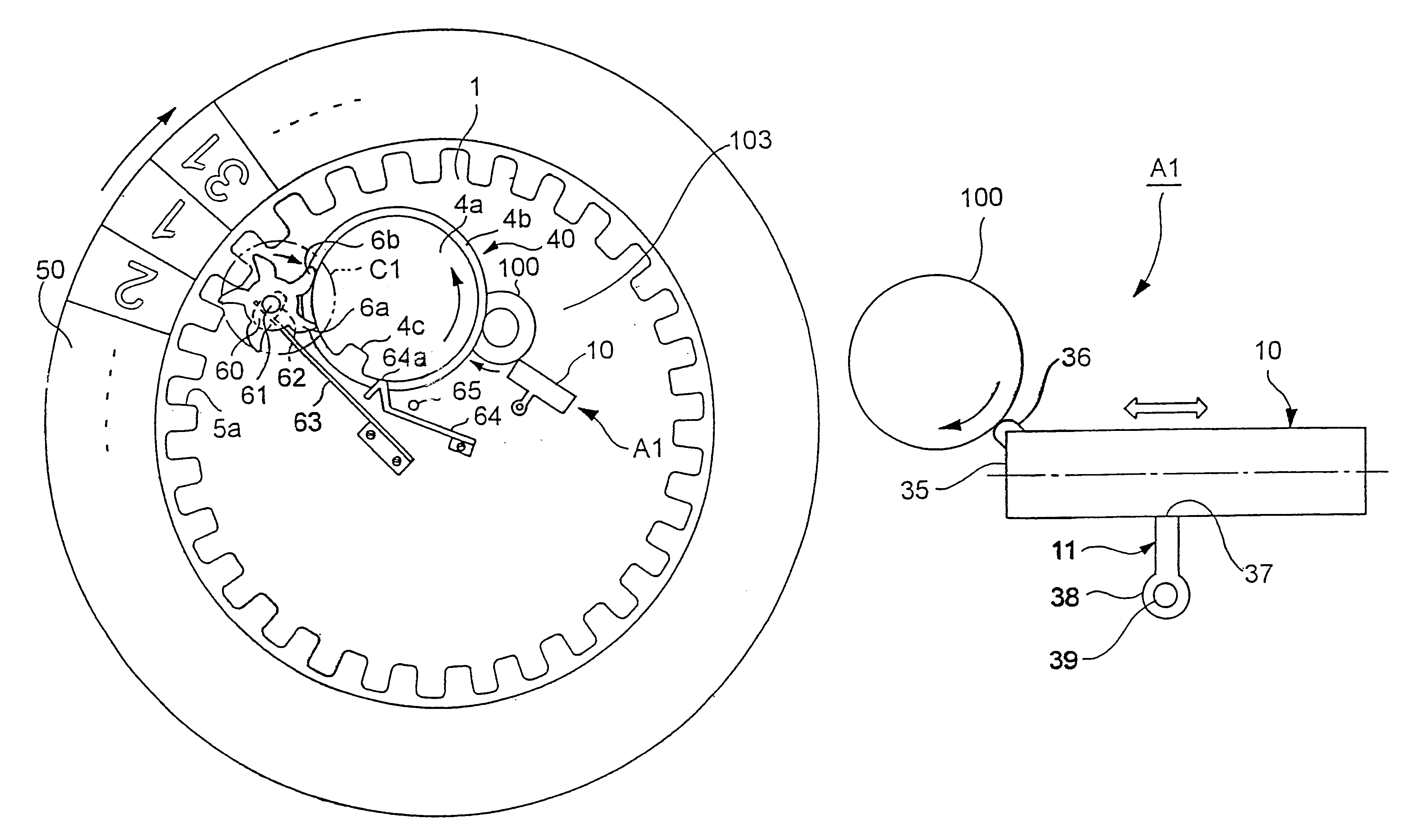
[0094]FIG. 1 is a plan view showing the principal construction of a calendar display mechanism having a piezoelectric actuator incorporated therein in a wristwatch according to a first embodiment of the present invention.

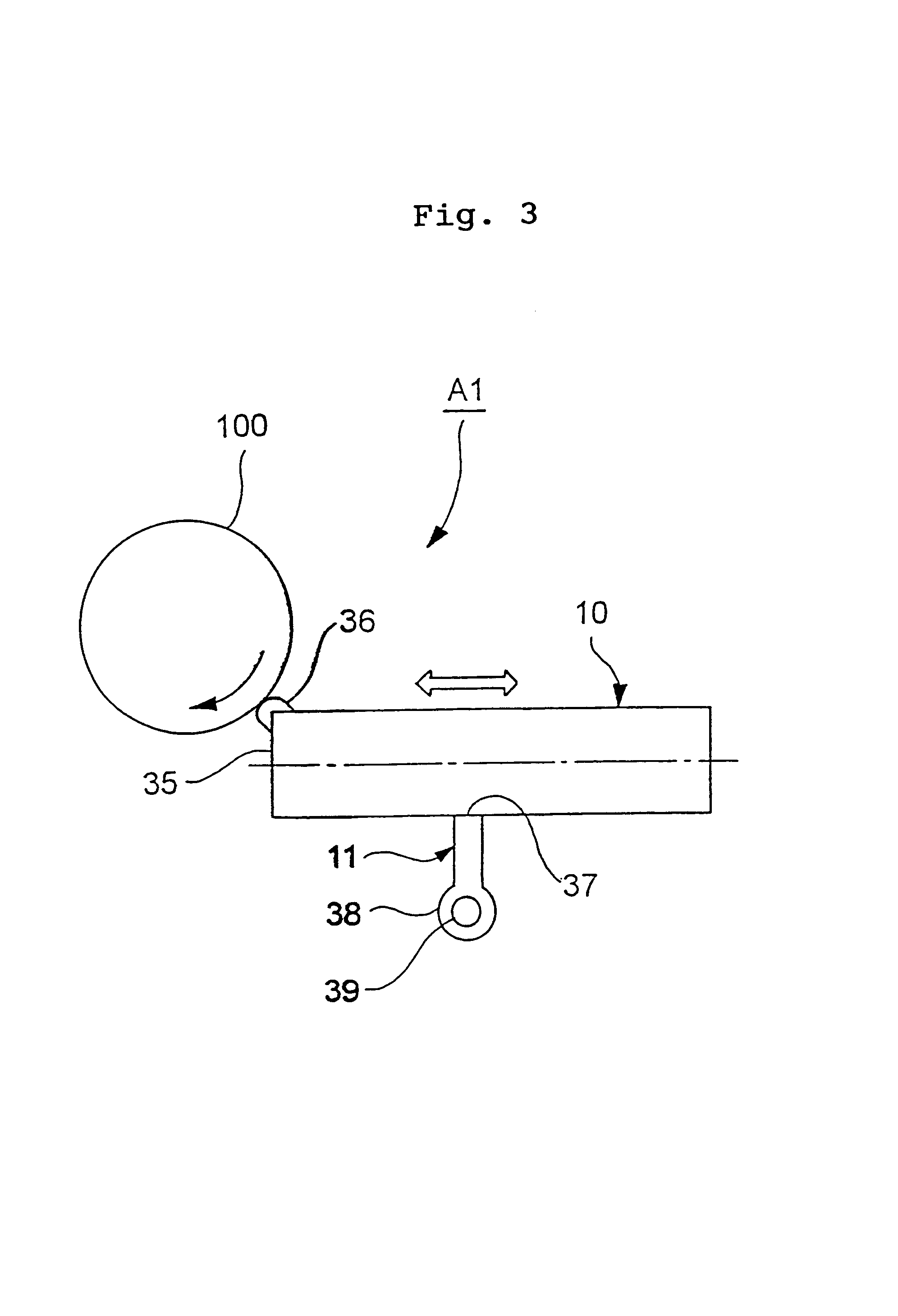
[0095]A piezoelectric actuator A1 is generally composed of a vibrating plate 10 that extensionally vibrates in an in-plane direction (a direction parallel to the plane of the figure) and a rotor (rotating member) 100. The rotor 100 is rotationally supported on a main plate (support body) 103, and is disposed at a position where it abuts against the vibrating plate 10. When its outer peripheral surface is tapped by vibrations generated in the vibrating plate 10, the rotor 100 is rotationally driven in a direction shown by the arrow in the figure.

[0096]Next, a calendar display mechanism is coupled to the piezoelectric actuator A1, and is driven by a driving force thereof. The principal part of the calendar display mechanism ...

first modification

A-7-1. First Modification

[0140]While the projection 36 is provided on the vibrating plate 10 at a contacting part between the projection 36 and the rotor 100 in the piezoelectric actuator A1 shown in the above-described embodiment, a cutout 90 may be formed by cutting out a peak of a rectangular vibrating plate 10 on the side of the rotor 100 so that the cutout 90 is brought into abutment with the side surface of the rotor 100, as shown in FIG. 20. In this case, a surface state of the cutout 90 can be easily controlled in a manner similar to the above-described projection 36. By forming the cutout 90 in the shape of a curved surface, a good contact state can be maintained in a manner similar to the above-described piezoelectric actuator A1.

second modification

A-7-2. Second Modification

[0141]While the electrodes 33 are provided on the entire surfaces of the piezoelectric elements 30 and 31 in the above-described embodiment, electrodes 33 may be disposed only near the longitudinal central parts of the piezoelectric elements 30 and 31 and may not be disposed on both ends, as shown in FIG. 21. That is, the piezoelectric elements 30 and 31 may be constructed so as to have electrode sections having electrodes on the surfaces thereof, and non-electrode sections located on both ends of the electrode sections. This construction makes it possible to reduce the drive voltage while maintaining the driving force to the rotor 100. This is because, when the vibrating plate 10 is vibrated with its natural vibration frequency, the both ends of the vibrating plate 10 are sufficiently greatly displaced by the vibration, and the displacement is not amplified even if a voltage is applied to the displaced portions so as to expand and contract the piezoelectri...


PUM


Abstract

A rectangular vibrating plate 10 in which a piezoelectric element and a reinforcing plate are stacked is supported on a main plate by a support member 11, and is urged toward the rotor 100 by an elastic force of the support member 11. This brings a projection 36 provided on the vibrating plate 10 into abutment with an outer peripheral surface of the rotor 100. In this construction, when the vibrating plate 10 vibrates in the horizontal direction in the figure by an applied voltage from a driving circuit (not shown), the rotor 100 is rotated in a clockwise direction in accordance with the displacement of the projection 36 due to the vibration.

Description

TECHNICAL FIELD[0001]The present invention relates to a piezoelectric actuator, and to a timepiece and a portable device including the piezoelectric actuator.BACKGROUND ART[0002]Since piezoelectric elements have excellent responsiveness and conversion efficiency from electrical energy to mechanical energy, various types of piezoelectric actuators utilizing the piezoelectric effect of piezoelectric elements have been developed in recent years. The piezoelectric actuators have been applied to the fields of piezoelectric buzzers, ink-jet heads of printers, and ultrasonic motors.[0003]FIG. 61 is a plan view schematically showing an ultrasonic motor using a conventional piezoelectric actuator. As shown in the figure, the ultrasonic motor of this type is called a poking type in which a rotor surface is slightly inclined and brought into contact with a tip of a vibrating piece connected to a piezoelectric element. In such a construction, when the piezoelectric element is expanded and contr...

Claims


Application Information

Patent Timeline
Patent Type & Authority Patents(United States)
IPC IPC(8): H01L41/09G04B19/24G04C3/12H02N2/00H02N2/10
CPCH01L41/0913H02N2/103H02N2/004H10N30/2023
Inventor MIYAZAWA, OSAMUHASHIMOTO, YASUHARUFUNASAKA, TSUKASAFURUHATA, MAKOTO
Owner SEIKO EPSON CORP
Why Eureka
Try Eureka