Hinge pin remover tool

Inactive Publication Date: 2005-05-03
WILSON SEAN F
View PDF5 Cites 33 Cited by
  • Summary
  • Abstract
  • Description
  • Claims
  • Application Information

AI Technical Summary

Benefits of technology

[0007]To paraphrase some of the more precise language appearing in the claims and further introduce the nomenclature used, the invention provides a tool for removing a hinge pin from a hinge when the hinge pin includes a hinge pin shaft with a predetermined hinge pin shaft diameter (e.g., {fraction (9/32)} of an inch) and a hinge pin head with a predetermined hinge pin head diameter (e.g., ½ of an inch) that is larger than the

Problems solved by technology

That is where certain problems can arise.
Over time, the hinge pin shaft often becomes tightly lodged in place, through corrosion or otherwise, making r

Method used


Image

  • Hinge pin remover tool
  • Hinge pin remover tool
  • Hinge pin remover tool

Examples


Embodiment Construction

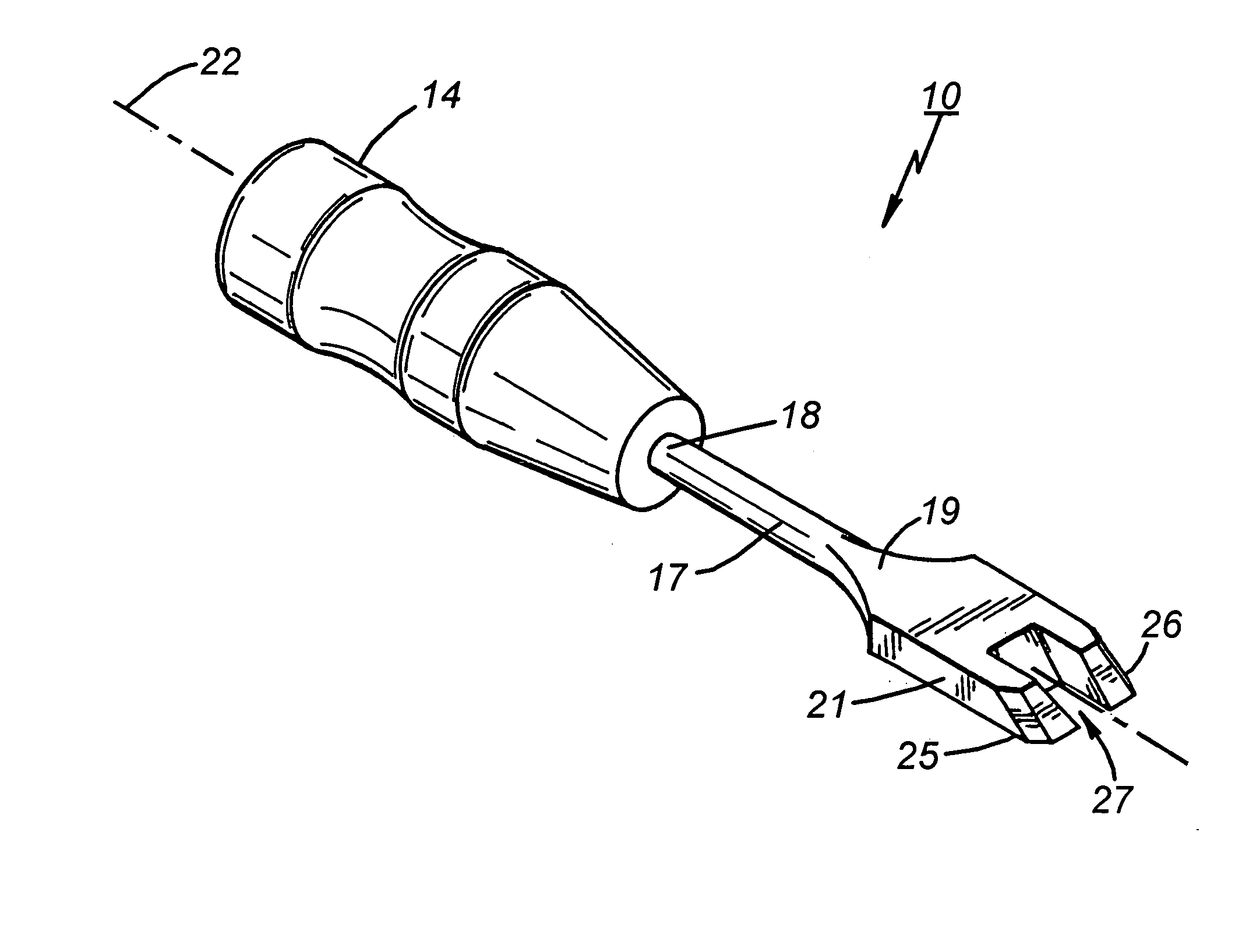
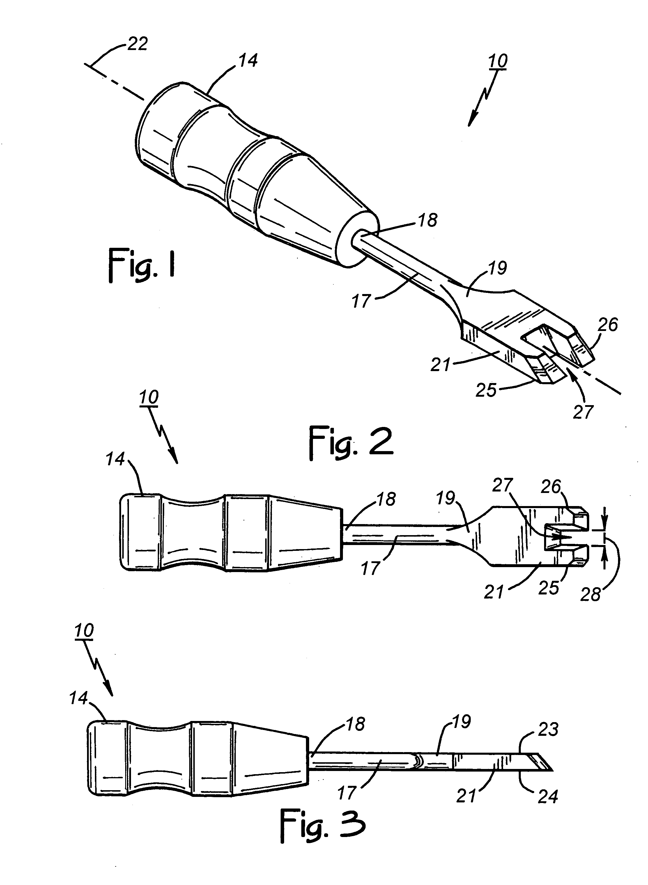
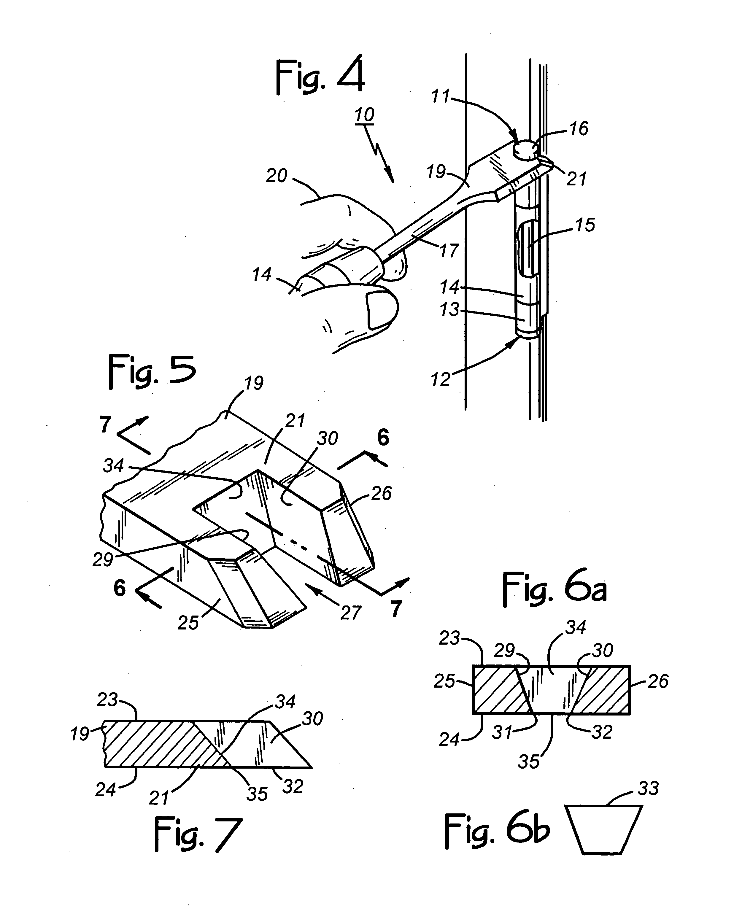
[0020]FIGS. 1–7 of the drawings show various aspects of a hinge pin remover tool 10 constructed according to the invention. It facilitates removal of a hinge pin 11 from a hinge 12 having first and second hinge sections 13 and 14 as shown in FIG. 4. The hinge pin 11 (typically made of steel) includes a hinge pin shaft 15 with a predetermined hinge pin shaft diameter (e.g., {fraction (9 / 32)} of an inch) and a hinge pin head 16 with a predetermined hinge pin head diameter (e.g., ½ of an inch) that is larger than the hinge pin shaft diameter.

[0021]Generally, the tool 10 includes an elongated member in the form of a blade 17 having a proximal end portion 18 and a distal end portion 19 identified in FIGS. 1–3. The blade 17 may be composed of quarter-inch thick steel, for example, similar to the blade of a typical screwdriver or chisel. The tool 10 also includes a handle 14 (FIGS. 1–4) that is attached to the proximal end portion 18 of the blade 17 for a user to grasp in a hand 20 of the ...


PUM

PropertyMeasurementUnit
Lengthaaaaaaaaaa
Lengthaaaaaaaaaa
Lengthaaaaaaaaaa

Abstract

A tool for removing a hinge pin from a hinge includes an elongated member having a proximal end portion and a distal end portion, a handle on the proximal end portion for a user to grasp in a hand of the user, and a forked tip on the distal end portion for the user to wedge between a hinge pin head and a hinge for purposes of facilitating hinge removal. The forked tip includes spaced apart first and second hinge-pin-dislodging tongs that define a channel having a width larger than the hinge pin shaft diameter and smaller than the hinge pin head diameter in order to enable the channel to receive the hinge pin shaft as the user wedges the first and second hinge-pin-dislodging tongs between the hinge pin head and the hinge.

Description

BACKGROUND OF THE INVENTION[0001]1. Technical Field[0002]This invention relates generally to hand tools, and more particularly to a hand tool for removing a hinge pin from a door hinge or other hinge.[0003]2. Description of Related Art[0004]A typical door hinge includes a first hinge section that mounts on a door and a second hinge section that mounts on a vertically disposed framing member at the door opening. The task of mounting a door on the framing member with multiple hinges proceeds by mounting the first and second hinge sections of each hinge on the framing member and the door. Next, the installer positions the door by the door opening and aligns the two hinge sections of each hinge. Then, the installer inserts removable hinge pins in the hinges that function to hold the two sections of the hinges together pivotally. The above applies to various types and kinds of hinges other than just door hinges. [0005]Removing the door proceeds in reverse order by first removing the hing...

Claims


Application Information

Patent Timeline
IPC IPC(8): B25B27/04B25B27/02
CPCB25B27/04Y10T29/53943Y10T29/53896
Inventor WILSON, SEAN F.
Owner WILSON SEAN F
Why Eureka
Try Eureka