Circular saw with improved cutting depth adjustment

a circular saw and depth adjustment technology, applied in the field of circular saws, can solve the problems of difficult to adjust difficulty in adjusting the depth of cut, and difficulty in adjusting the depth of cut, and achieve the effect of simple structure and accurate adjustment of the cut depth

Inactive Publication Date: 2005-05-03
MAKITA CORP
View PDF16 Cites 30 Cited by
  • Summary
  • Abstract
  • Description
  • Claims
  • Application Information

AI Technical Summary

Benefits of technology

[0008]In view of the above-identified problems, an important object of the present invention is to provide a circular saw that realizes accurate adjustment of the depth of cut with a simple structure.
[0009]The above object and other related objects are realized by the invention, which provides a circular saw comprising: a generally rectangular base; a guide member disposed on the base; and a main body having forward and back ends, a motor, and a saw blade which is rotatably driven by the motor and has side faces, in which the forward end of the main body is coupled to the base so as to permit the main body to pivot along the side faces of the blade relative to the base, and the rear end of the main body is adapted such that it can be secured to any position along the guide member such that the amount of the blade protruding below the base can be changed by pivotally moving the main body and securing the rear end to any position along the guide member. In the circular saw, the main body includes a stopper whose position relative to the main body with respect to the base is changeable and which is brought into abutment with the base by the pivotal movement of the main body so as to limit the pivotal movement of the main body, such that the amount of the blade protruding below the base can be set by selection of the position of the stopper relative to the main body with respect to the base. This arrangement realizes easy and accurate setting of the depth of cut in workpieces.
[0010]According to one aspect of the present invention, the stopper is coupled to the main body so as to be pivotal on an axis toward the base, and the stopper includes securing means for securing the stopper to the main body at a desired pivotal position. This arrangement stabilizes the abutment of the stopper against the base and thus realizes more accurate settings of the depth of cut in workpieces.

Problems solved by technology

While this arrangement achieves its intended objective, it is not free from certain problems and inconveniences.
Such settings are often performed by measuring with carpenters square the amount of the blade protruding below the base, rendering the task cumbersome, often producing inaccurate results.
This problem is particularly exacerbated in bevel cutting since accurate setting of the depth of cut becomes even more difficult with a tilted blade.

Method used


Image

  • Circular saw with improved cutting depth adjustment
  • Circular saw with improved cutting depth adjustment
  • Circular saw with improved cutting depth adjustment

Examples


Embodiment Construction

[0027]A preferred embodiment of the present invention will be described hereinafter with reference to the attached drawings.

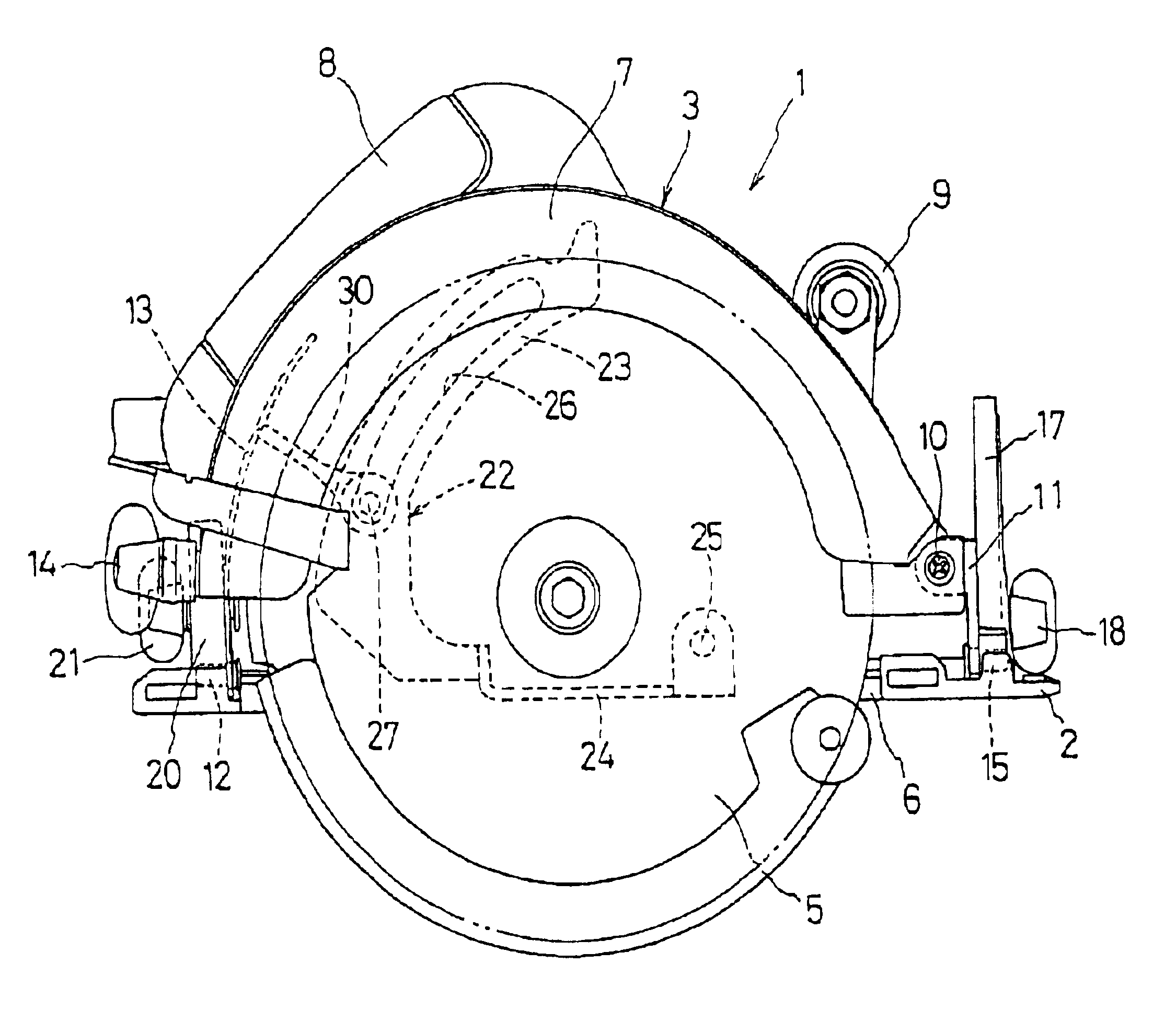
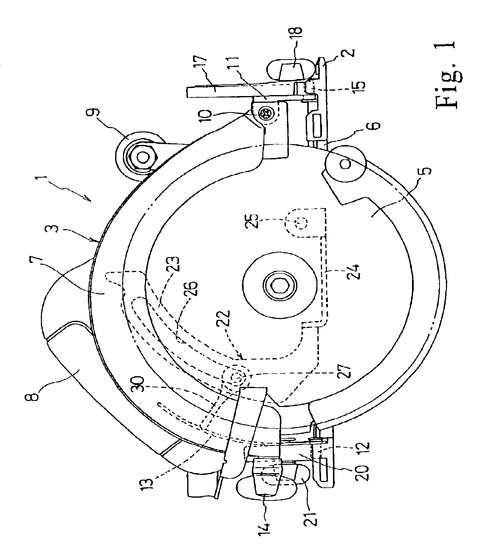
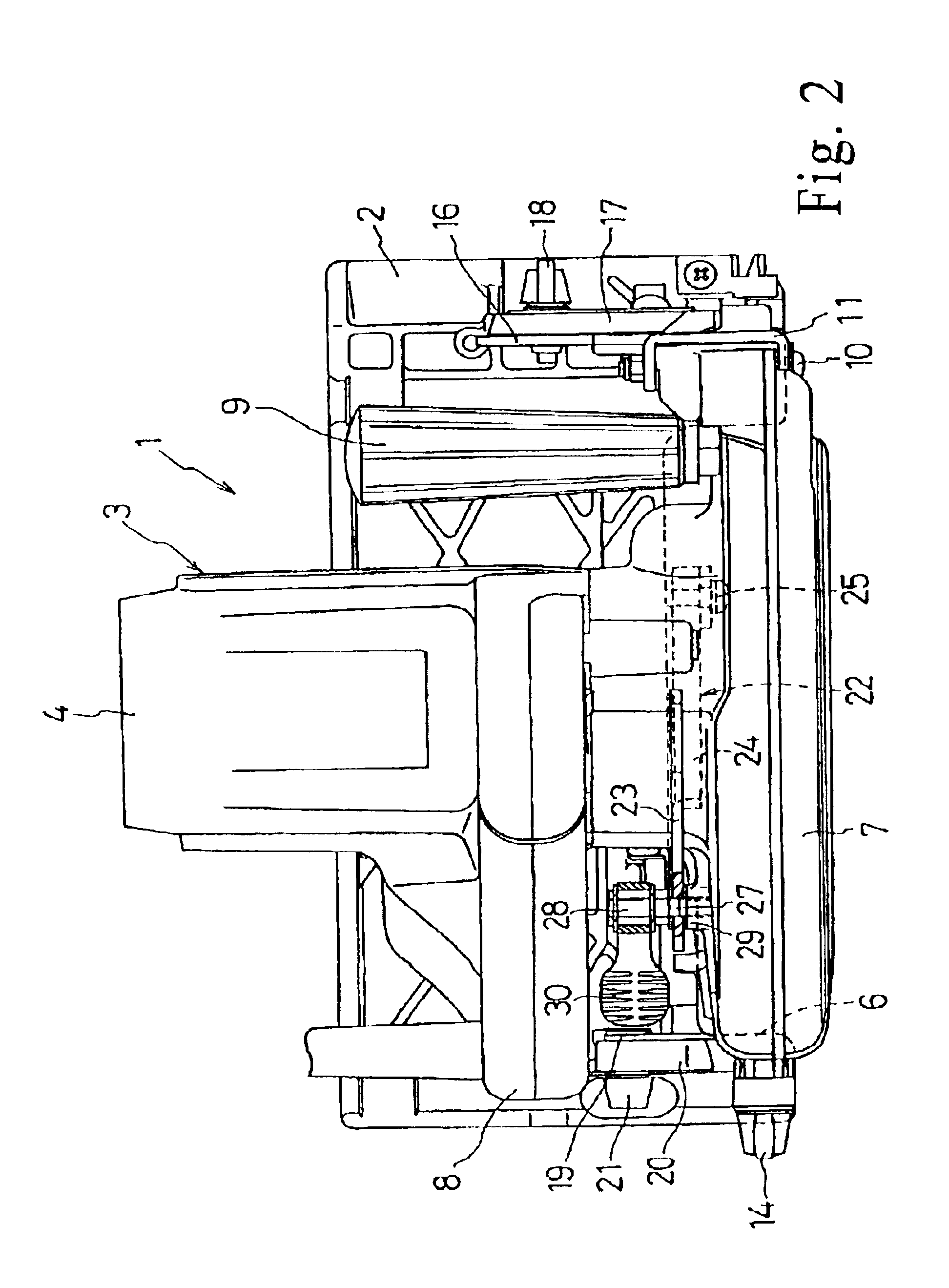
[0028]FIG. 1 is a front view of a corner-cutting circular saw 1 according to the present invention and FIG. 2 is a plane view of the corner-cutting circular saw 1. The circular saw 1 includes a generally flat rectangular base 2 and a main body 3 mounted on the base 2. The main body 3 includes a circular or disk-shaped blade 5 disposed generally on the front side thereof and a motor housing 4 encasing a motor (not shown) disposed on the opposite rear side thereof. The saw blade 5 is coupled to and driven by the motor for cutting. The main body 3 is disposed on the base such that the saw blade 5 is oriented parallel with a longitudinal front edge of the base 2 and projects below the base 2 through a recess 6 formed in the longitudinal front edge of the base. The main body 3 further includes an upper blade guard 7 covering the upper portion of the saw blade 5 and ...


PUM

PropertyMeasurementUnit
tilt angleaaaaaaaaaa
anglesaaaaaaaaaa
angleaaaaaaaaaa

Abstract

A circular saw (1) includes a base (2) and a main body (3) mounted on the base and provided with an upper blade guard (7). Disposed behind the upper blade guard (7) is a stopper (22) which includes an upper curved portion (23) and an lower portion (24) coupled to the curved portion (23). One end of the lower portion (24) is attached to the main body (3) with a pivot screw (25) behind the blade guard (7) so as to permit the stopper to pivot on the screw (25) in parallel with a circular blade (5). Additionally, the curved portion (23) includes an arcuate guide slot (26). The stopper (22) further includes a fixing bolt (27) screwed in a boss (29) formed on the rear surface of the blade guard. The bolt (27) includes a lever (30) to be manually operated to selectively secure the curved portion to the bolt and release the curved portion therefrom. When the curved portion (23) is released, its pivotal position relative to the main body towards the base can be manually changed. Provided on the base is a projection (32) which is abutted by the stopper (22) when the main body (3) is lowered toward the base (2). When the curved portion (23) abuts the projection's upper surface (33), the amount of the blade (5) projecting below the base (i.e., the depth of cut) corresponds to the aforementioned relative position of the curved portion (23) with respect to the base (2).

Description

[0001]This application claims priority on Japanese Patent Application No. 2001-235411 filed on Aug. 2, 2001, the entire contents of which are incorporated herein by reference.BACKGROUND OF THE INVENTION[0002]1. Field of the Invention[0003]The present invention generally relates to electric power tools. More particularly, the present invention relates to a disk-shaped saw having a base and a motor-driven circular blade mounted on the base.[0004]2. Description of the Related Art[0005]A typical circular saw includes a generally rectangular base and a main body mounted on the base. The main body in turn includes a motor-driven disk-shaped blade disposed generally on one side thereof and a motor housing encasing a motor disposed on the opposite side thereof. The forward end of the upper blade guard (adjacent to the cutting end of the saw blade) is coupled via a pivot shaft and a support member to the base in a manner that permits the blade guard to pivot about the shaft along the side fa...

Claims


Application Information

Patent Timeline
Patent Type & Authority Patents(United States)
IPC IPC(8): B27B9/00B27B9/02
CPCB27B9/02
Inventor KANI, TOSHIYUKI
Owner MAKITA CORP
Why Eureka
Try Eureka