Dual stage inflator

Inactive Publication Date: 2005-05-03
KEY SAFETY SYST
View PDF9 Cites 50 Cited by
  • Summary
  • Abstract
  • Description
  • Claims
  • Application Information

AI Technical Summary

Problems solved by technology

This patent fails to suggest a multi-stage inflator that is specifically tailored for driver side use.
More specifically, U.S. Pat. No. 6,149,193 does not

Method used


Image

  • Dual stage inflator
  • Dual stage inflator
  • Dual stage inflator

Examples


Embodiment Construction

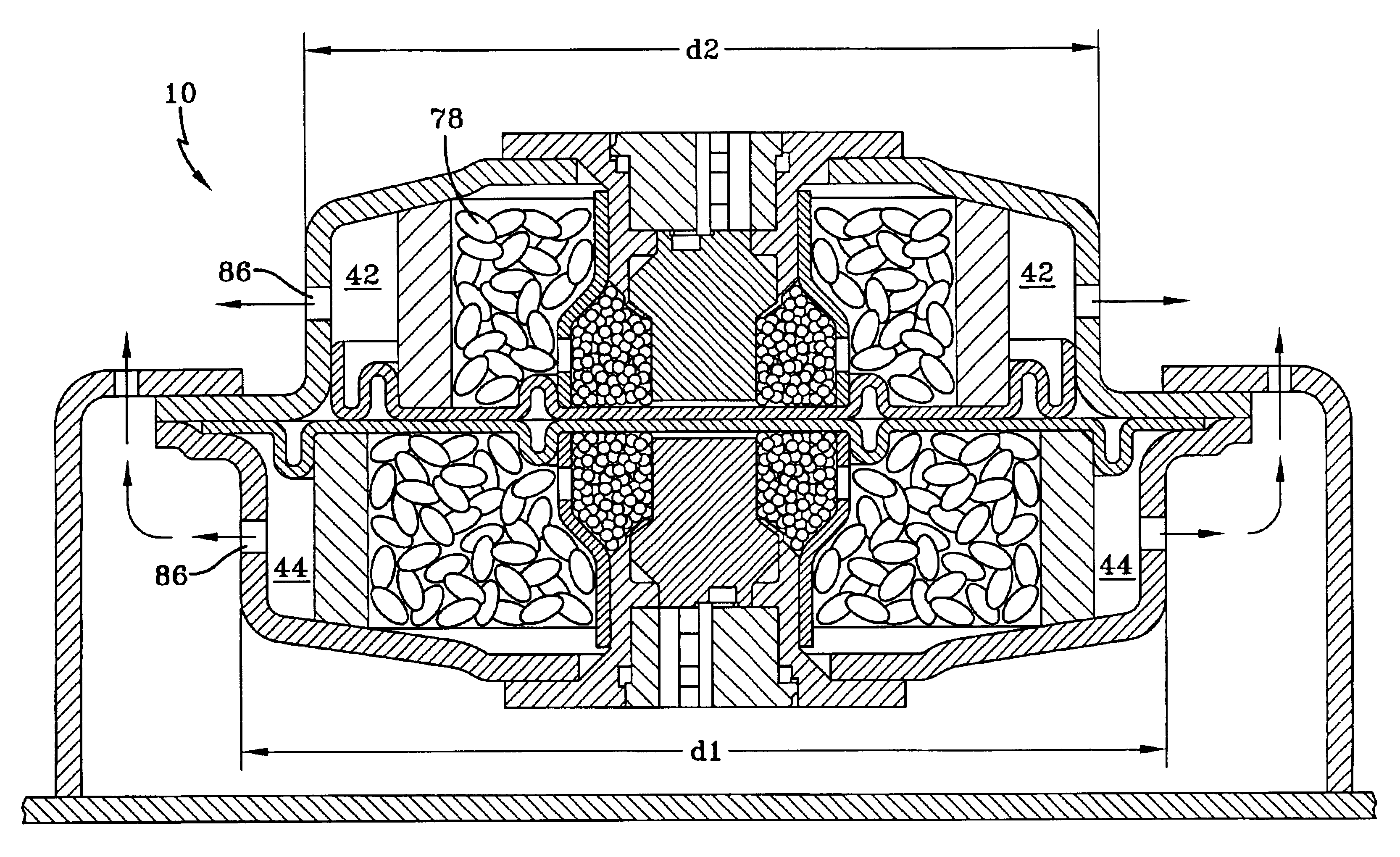
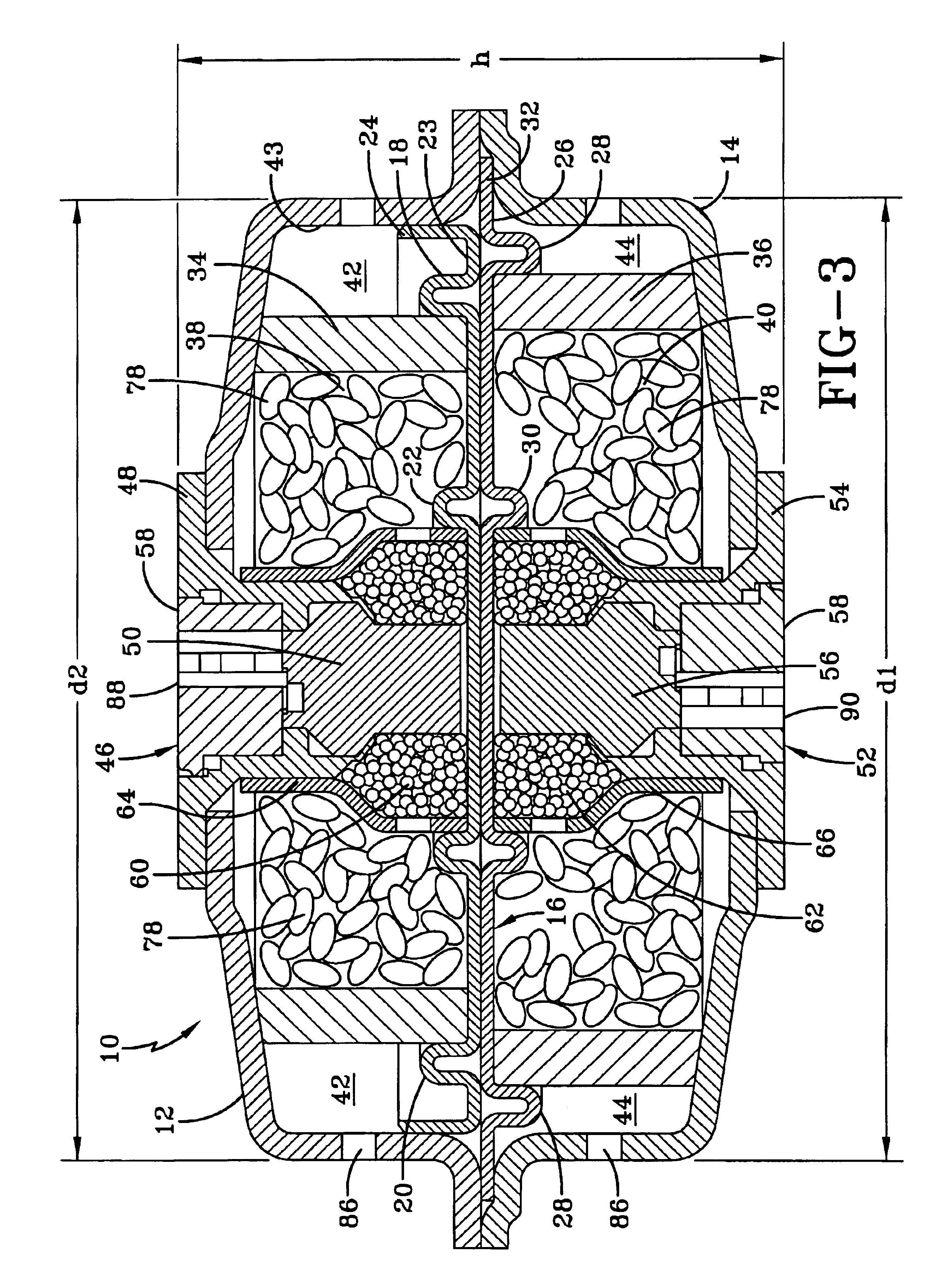
[0022]Referring now to the drawings wherein the showings are for purposes of illustrating a preferred embodiment of the invention only and not for purposes of limiting the same, FIGS. 1-3 show an inflator 10 for use with an associated vehicle occupant airbag system. The embodiment illustrated is intended for use on the driver's side of an associated vehicle, and the invention is also applicable to inflators used for passenger side vehicle occupant restraint assemblies and other uses as well. The inflator 10 comprises two housing portions 12, 14. The first housing portion 14 defines a first propellant chamber 40 and the second housing portion 12 defines a second propellant chamber 38.

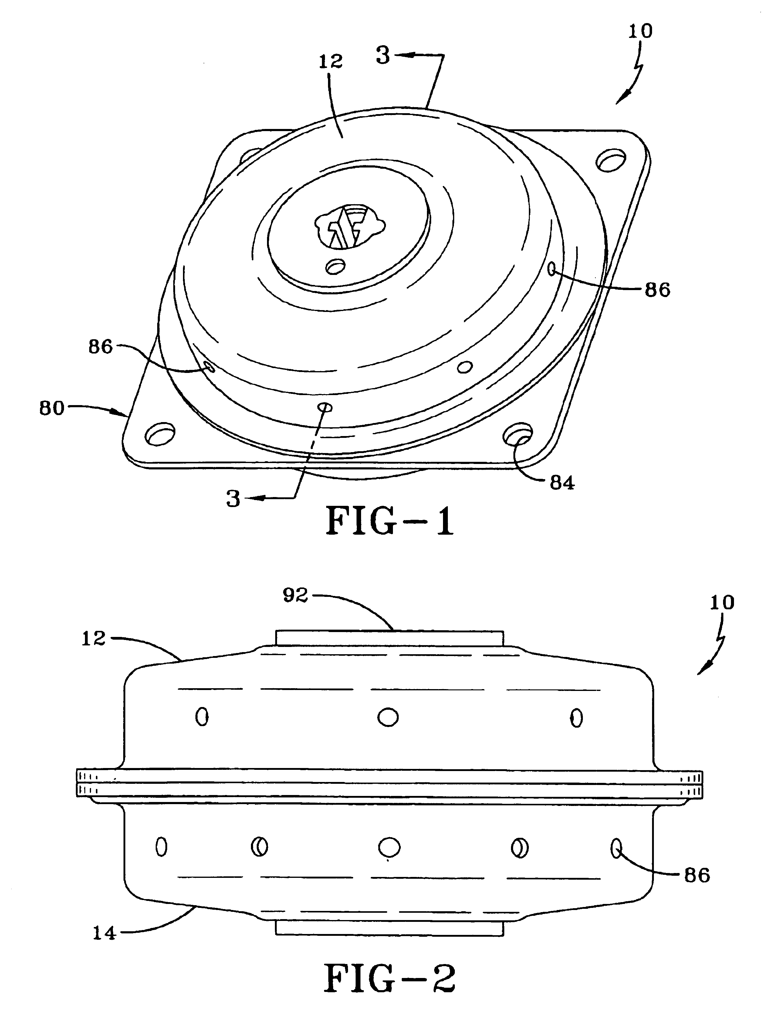
[0023]As shown in FIG. 9 the inflator 10 has a flange 80 used to attach the inflator to a vehicle. The flange 80 has a plurality of holes 84 therethrough. Fasteners, such as bolts can be inserted through the holes 84 to secure the inflator 10 and an associated airbag (not shown) to a mounting plate (not ...


PUM


Abstract

An inflator for inflating an airbag has a housing with a first housing portion defining a first chamber and a second housing portion defining a second chamber. A gas generant disposed in the first and second chambers. A barrier separates the first and second chambers. Each of the chambers has an ignition enhancer tube disposed therein with a portion of an ignition unit being located therein. Each of the ignition enhancer tubes has at least one outlet defined therein. Each ignition enhancer tube holding an ignition enhancer such that when the associated ignition unit ignites the ignition enhancer combusts and exits through said outlet and then reacts with the gas generant in the associated chamber.

Description

FIELD OF THE INVENTION[0001]The present invention relates to an inflator for inflating an airbag in a vehicle occupant restraint system, and more specifically for an inflator having two independent combustion chambers.BACKGROUND OF THE INVENTION[0002]An automotive airbag system protects vehicle occupants in crashes by rapidly inflating a cushion or bag between a vehicle occupant and the interior of the vehicle. The inflated airbag absorbs the vehicle occupant's energy to provide a gradual, controlled deceleration and provides a cushion to distribute body loads and keep the vehicle occupant from impacting the hard surfaces of the vehicle interior.[0003]Historically, inflators have been single staged containing only one igniter, so that only one rate of inflation could be obtained. However; multi-stage inflators were developed, which had multiple igniters and allowed the rate of airbag inflation to be controlled or staged such that the airbag may be inflated at varying rates during a ...

Claims


Application Information

Patent Timeline
IPC IPC(8): B60R21/26B60R21/264
CPCB60R21/2644B60R2021/2648B60R2021/2633
Inventor CANTERBERRY, J BBOWERS, DONALD
Owner KEY SAFETY SYST
Why Eureka
Try Eureka