Automobile bumper structure

a bumper structure and automobile technology, applied in the direction of bumpers, vehicle components, radiators, etc., can solve the problems of increasing the number of fastening positions, the difficulty of assembling, and the number of parts, so as to improve the assemblage, keep the number of parts from increasing, and keep the cost from increasing

Inactive Publication Date: 2005-05-03
MAZDA MOTOR CORP
View PDF18 Cites 49 Cited by
  • Summary
  • Abstract
  • Description
  • Claims
  • Application Information

AI Technical Summary

Benefits of technology

[0010]In view of the above described problems, it is an object of the present invention to provide an automobile bumper structure which is capable of improving its assemblage, keeping the number of parts from increasing, keeping costs from heightening, and in addition, preventing a pedestrian or the like from suffering a more severe blow without getting caught under a vehicle when the pedestrian or the like has been hit by the vehicle.
[0013]According to this first aspect, there is no need for any attachment member used exclusively as a reinforcement member, such as a bracket shown in the prior arts. This keeps costs from heightening and improves its assemblage. In addition, the reinforcement member can be disposed at a lower part of the bumper, thereby preventing a pedestrian or the like from getting caught behind the reinforcement member, or under a vehicle, when the pedestrian or the like has been hit by the vehicle.

Problems solved by technology

However, this structure increases the number of parts, thereby making its assemblage difficult.
It also increases the number of fastening positions, requiring many fastening parts.
This makes production costs higher.
This is expected to make injuries sustained to that body part more severe.
However, the impact absorbing body 110, which is a reinforcement member that prevents a pedestrian or the like from getting caught under the vehicle body, is made of resin and is supported only on one side with the frame 106, thereby weakening its supporting rigidity.

Method used


Image

  • Automobile bumper structure
  • Automobile bumper structure
  • Automobile bumper structure

Examples


Embodiment Construction

[0040]Hereinafter, the automobile bumper structure according to embodiments of the present invention will be described in detail with reference to the accompanied drawings. However, the present invention is not limited to the embodiments described below.

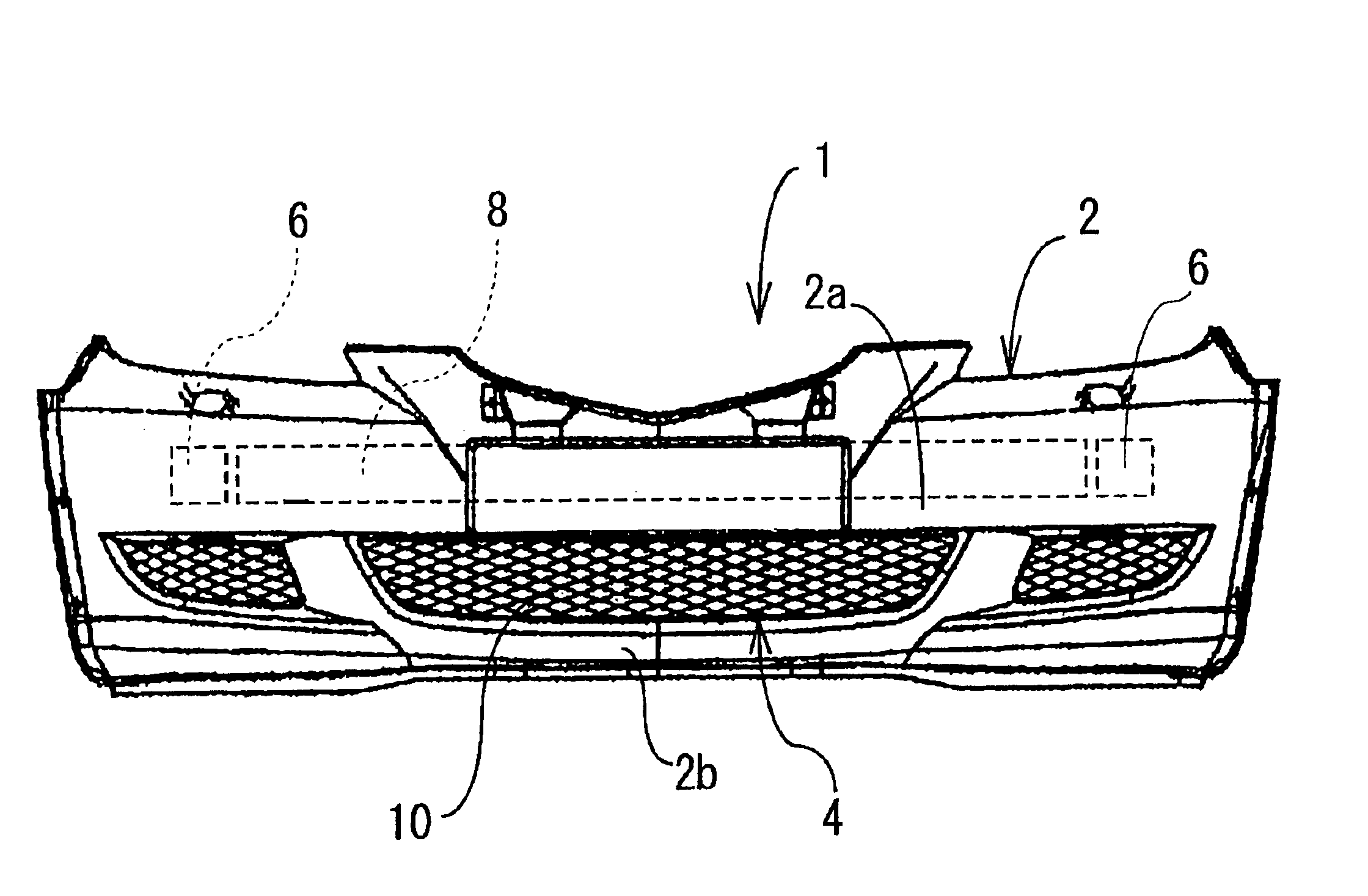
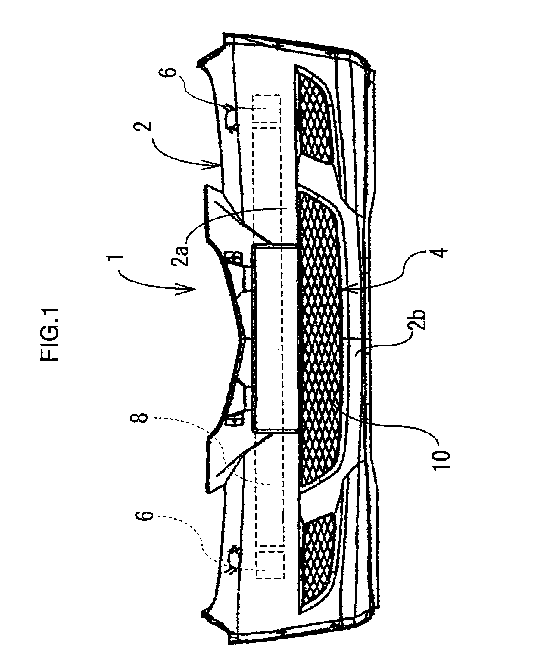
[0041]FIG. 1 is a front view of an automobile bumper structure body 1 according to the present invention. This bumper structure body 1 is configured by: a bumper face 2; a grille 10; a crush cant 6; a bumper reinforcement 8; and others, and is incorporated in the front part of a vehicle body. This crush cant 6 and the bumper reinforcement 8, which are used for absorbing energy at the time of a bump, are placed on the back-surface side of a bumper upper face 2a. The bumper face 2 is made up of the bumper upper face 2a and a bumper lower face 2b, which are united by injection molding. Between the bumper upper face 2a and the bumper lower face 2b, an opening portion 4 is formed which is long in the vehicle-width directions. In the openi...


PUM


Abstract

An automobile bumper structure is provided which is capable of keeping down an increase in weight, strongly supporting a reinforcement member with a vehicle structure body behind it, preventing a pedestrian or the like from getting caught under a vehicle when the vehicle has hit the pedestrian or the like. In this automobile bumper structure, a bumper face 2 includes an opening portion 4, and a reinforcement member 20 is disposed behind and inside of a bumper lower face 2b which extends downward from this opening portion 4. Side-plane portions 22, an upper-plane portion 24, a front-plane portion 26 and a lower-plane portion 28 are formed in the reinforcement member 20. A vertical rib 32 is provided across the upper-plane portion 24, the front-plane portion 26 and the lower-plane portion 28. An extended portion 29 is united with the lower-plane portion 2 and extends rearward from it, and this extended portion 29 is connected to a cross member which is disposed behind a bumper structure body 1 and is also connected to an under cover.

Description

BACKGROUND OF THE INVENTION[0001]1. Field of the Invention[0002]This invention relates to an automobile bumper structure.[0003]2. Description of the Related Art[0004]With respect to an automobile bumper structure, a structure is known as shown in FIG. 16A and FIG. 16B (refer to Japanese Patent Laid-Open No. 2002-205613 specification). Herein, FIG. 16B is a sectional view of the structure, seen along a Y9—Y9 line in FIG. 16A. This structure is configured by: right and left bracket bodies 135 whose rear-end parts are each supported via an attachment plate 136 and which are curved toward the rear of a bumper face under 126 and each extend to a front side frame (not shown); a hollow body 150 which is connected to these right and left bracket bodies 135 between them via an attachment plate 132; a vertical rib 152 and a lateral rib 151 which are provided on the front surface of the hollow body 150; and others.[0005]However, this structure increases the number of parts, thereby making its ...

Claims


Application Information

Patent Timeline
Patent Type & Authority Patents(United States)
IPC IPC(8): B60R19/56B60R19/52B60R19/00B60R19/18B60R21/34B60R19/12
CPCB60R19/12B60R19/18B60R19/52B60R2019/527B60R2019/1846B60R2019/1886B60R21/34
Inventor MATSUMOTO, TAKAOFURUMOTO, ARIHIRO
Owner MAZDA MOTOR CORP
Why Eureka
Try Eureka