Golf club

a golf club and club technology, applied in the field of golf clubs, can solve the problems of not being able to solve the problem completely satisfactorily, not being able to completely solve the problem, and the restitution force decreases, so as to achieve the effect of improving the restitution for

Inactive Publication Date: 2005-05-03
ENDO MFG COMPANY
View PDF11 Cites 212 Cited by
  • Summary
  • Abstract
  • Description
  • Claims
  • Application Information

AI Technical Summary

Benefits of technology

[0014]An object of the present invention is to provide a golf club with improved restitution force in a lower position on the face portion such that carry does not decrease when a ball is struck not only in the conventional sweet area, but also in the portion below the conventional sweet area.
[0015]Another object of the present invention is to provide a golf club in which, by altering only a part of the sole portion rather than altering the conventional shape of the club, conventional hitting performance can be improved upon without altering the basic conventional shape of the club.
[0016]A further object of the present invention is to provide a golf club which can be mass-produced at low cost.
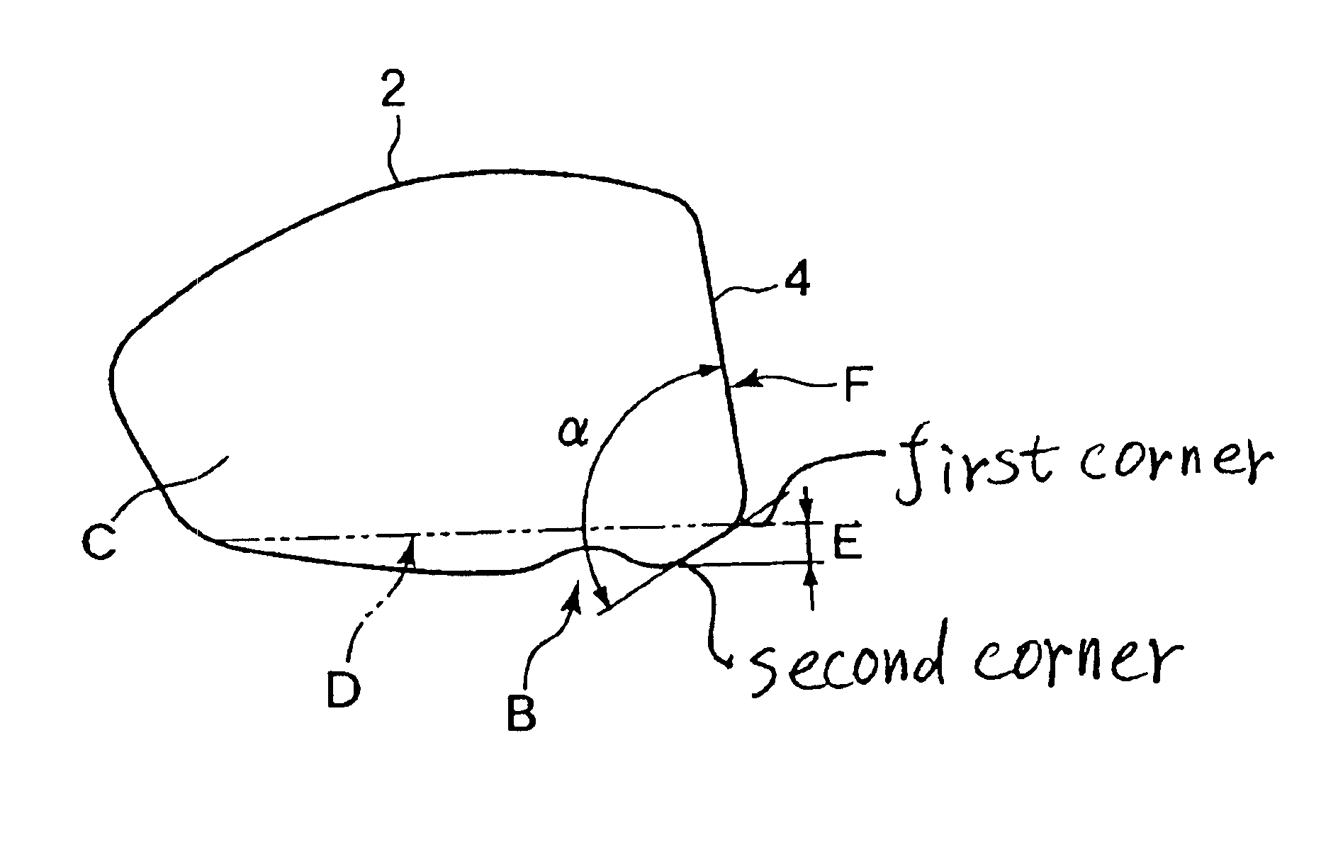
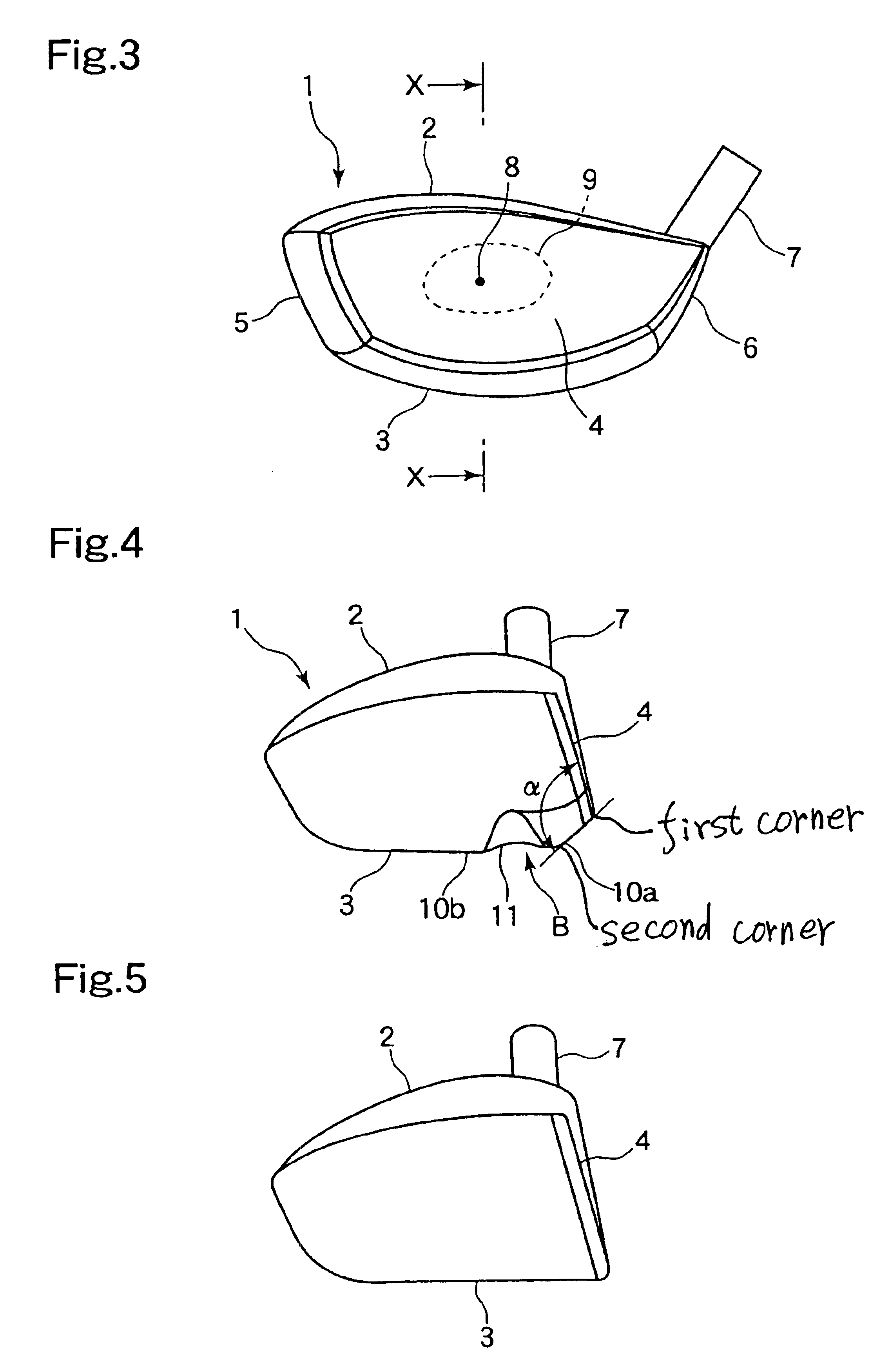
[0022]In a golf club of a fifth invention, the deformation portion in the golf club of the first invention comprises a protruding part which protrudes such that the sole portion is formed, in continuation with the hitting surface and the face portion, in an obtuse angle as viewed in a cross section cut along a vertical plane including a perpendicular to the hitting surface in order to enhance an elastic effect.

Problems solved by technology

As a result, however, restitution force decreases and carry is not as great as when the ball is struck on the sweet area.
As described above, techniques have been designed for increasing carry under various conditions, but none have solved the problem completely satisfactorily.
However, although this method is effective under specific circumstances, the restitution effect is not reliably enhanced in the lower direction of the face portion.
Further, although the method of providing a dead weight is effective in itself, there are limitations on the recent trend of enlarging the head.
More specifically, when the head is enlarged, a new problem arises in that the mass of the club head increases with the addition of the dead weight.
When the shape, mass, and so on of the head are greatly altered, a player may suffer adverse effects such as having to alter his / her swing, losing his / her rhythm, and so on.
Even if an innovative club were to be developed, a long period of time would be required for the club to become established in practice.

Method used


Image

  • Golf club
  • Golf club
  • Golf club

Examples


example

[0055]An example of performance improvement relating to these constitutions will now be described. FIG. 11 illustrates the results of an experiment applied to the golf club of the first embodiment of the present invention. FIG. 11 shows the distribution of coefficients of restitution when a golf ball is struck on the face portion 4. On the basis of the experiment results, the positions of identical coefficients of restitution are plotted on the drawing as contour lines. FIG. 12 shows the results of an experiment performed under identical conditions to that in FIG. 11 in respect of a conventional golf club. The experiment was performed under the following conditions.[0056]Face portion material: cold-rolled Ti-15 V-3 Cr-3 Sn-3 Al material; plate thickness 2.9 mm[0057]Sole portion material: Ti-15 V-3 Cr-3 Sn-3 Al; plate thickness 1.15 mm[0058]Crown portion material: Ti-15 V-3 Cr-3 Sn-3 Al; plate thickness 1.0 mm[0059]Volume: approx. 300 cc; mass: approx. 196 g.

[0060]When FIGS. 11 and 1...


PUM


Abstract

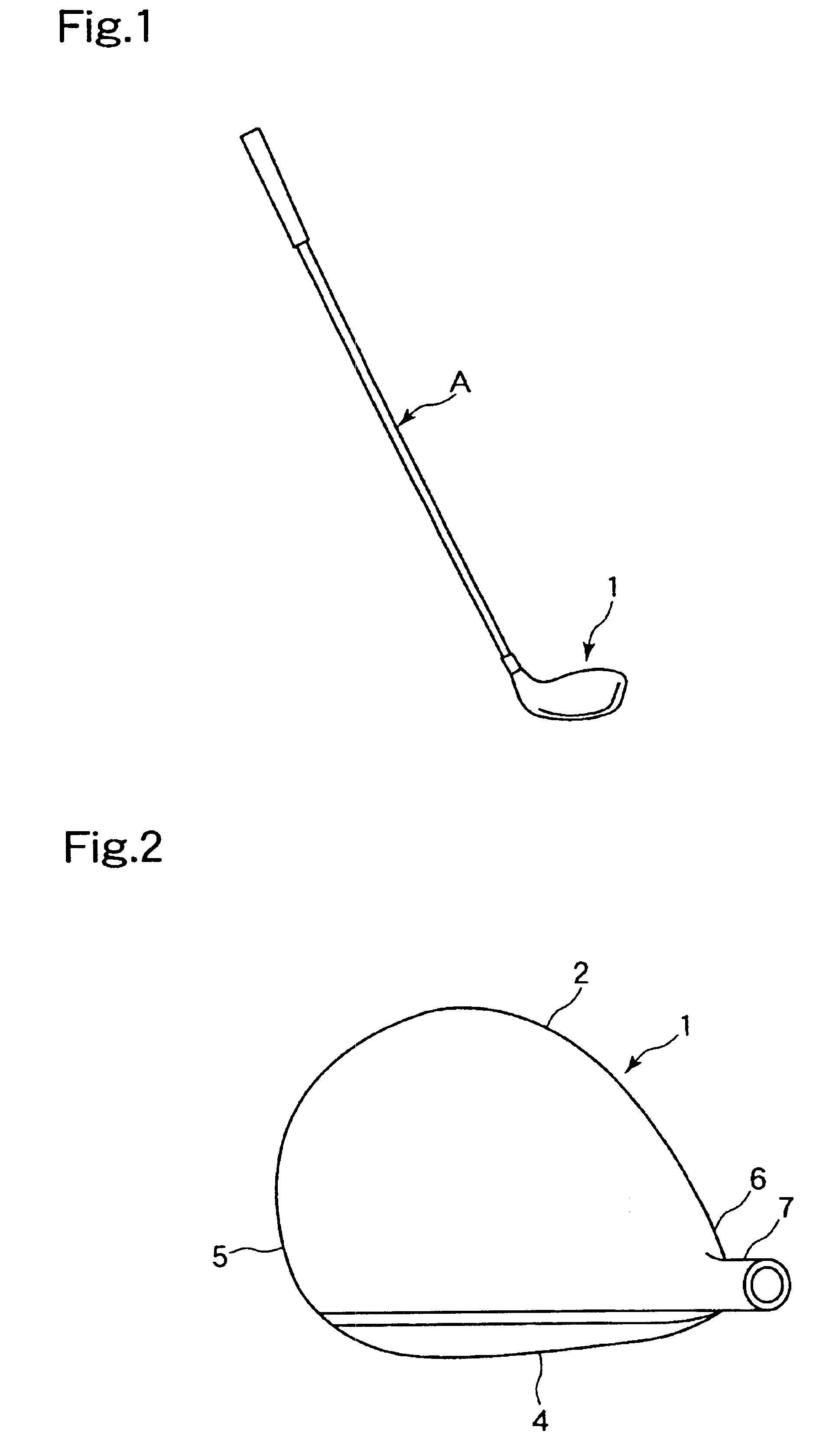
A golf club provides carry which does not deteriorate even when a golf ball is struck in a lower position on a face portion. The golf club includes a face portion 4 having a hitting surface, an improved sole portion 3 which forms a lower portion, and a crown portion 5 which forms an upper portion. A deformation portion B which is capable of elastic deformation is provided in concavoconvex form on the sole portion 3 in a position near the face portion 4. This deformation portion B is constituted by a protrusion 10 which is formed such that the sole portion 3 forms an obtuse angle α, and a concave groove 11 which is formed in a direction linking a toe portion and a heel portion by a protrusion protruding towards the crown portion 5.

Description

BACKGROUND OF THE INVENTION[0001]1. Field of the Invention[0002]The present invention relates to a golf club, and more particularly to a golf club having an improved sole portion for enhancing carry.[0003]2. Description of the Related Art[0004]Various golf clubs are prepared in accordance with the conditions of a course. For the tee-off, a golf club known as a driver is used to extend the carry. Since the carry directly influences the quality of the score, the position of the point of contact on the head of the golf club is an important element. The contact surface of a golf club is known as the face, and a user only ever hits a ball with the face, regardless of the playing conditions.[0005]The center of gravity of a golf club when projected onto the face of a driver club head is usually positioned above the central portion of the face when seen from a perpendicular direction to the face. When the shape of the face is observed, it can be seen that the upper face side is wide and the...

Claims


Application Information

Patent Timeline
Patent Type & Authority Patents(United States)
IPC IPC(8): A63B53/04
CPCA63B53/0466A63B2053/0408A63B2053/0412A63B2053/0462A63B2053/0458A63B2209/00A63B2053/0433A63B53/0412A63B53/0408A63B53/0462A63B53/0433A63B53/0458
Inventor TSURUMAKI, MASAEI
Owner ENDO MFG COMPANY
Why Eureka
Try Eureka