Multi-layer metallic structure and composite-to-metal joint methods

a multi-layer metallic structure and composite technology, applied in the field of composite structures, can solve the problems of increasing structure weight, titanium fittings, and relatively high cost, and achieve the effect of reducing or eliminating the possibility of corrosion and/or problems, reducing the occurrence and/or propagation, and reducing the possibility of bending load

Active Publication Date: 2015-03-31
THE BOEING CO
View PDF146 Cites 38 Cited by
  • Summary
  • Abstract
  • Description
  • Claims
  • Application Information

AI Technical Summary

Benefits of technology

[0008]The disclosed embodiments provide a hybrid-type composite structure that includes a fiber reinforced resin composite-to-metal joint that may be used to connect a substantially all-metal fitting with a substantially all composite resin structure or a different structure. The joint provides a transition between the composite and metallic structures that is suitable for use in higher performance applications, such as aerospace vehicles. This transition from a substantially all composite to a substantially all metal material may reduce or eliminate the possibility of corrosion and / or problems stemming from eccentricity. During lay-up of the composite structure, relatively thin, flexible metal sheets of metal are substituted for a number of composite plies, and the transition from composite plies to metal sheets occurs at staggered locations so as to provide adequate load transfer from the composite portion to the metal portion. The staggered transition results in an interleaving between the composite plies and the metal sheets and creates multiple bond lines that may reduce the occurrence and / or propagation of cracks or disbonds in the joint. An adhesive placed between the metal sheets binds and unitizes the sheets into a nearly solid metal fitting.
[0009]The composite-to-metal joint may be configured as a finger type, step lap joint in order to reduce residual stresses that may be induced in the joint during cooling of the hybrid composite structure following a thermal cure cycle. The bonded metal sheets employed in the joint form a metal laminate that may be used in a variety of other applications, and which exhibits improved performance compared to monolithic metal structures. In some applications, the composite-to-metal joint utilizing the metal laminate may be used to reinforce an edge of a composite structure or to reinforce an area of a composite structure around fasteners. Additional advantages of the disclosed composite-to metal joint may include improved joint robustness, reduced weight, improved safety, less maintenance, weight savings, improved inspectability, strength improvements, and reduced manufacturing costs. The disclosed metal laminate used in the composite-to-metal joint may enable a structure to have weight and fatigue characteristics of composite resin laminates while providing the strength and durability of a metal structure. The composite-to-metal joint may reduce or avoid the need for machined end-fittings for some composite resin structure applications. A shorter bond length resulting from use of the disclosed joint may minimizes residual (or cured in) stresses due to CTE (coefficient of thermal expansion) mismatch between the metallic and composite materials forming the joint, and may also benefit the in-service performance of the joint where service temperatures can vary 225 degrees F. or more.
[0010]According to one disclosed embodiment, a metal structure is provided that exhibits improved strain performance. The metal structure comprises at least a first metal laminate including a first plurality of metal sheets bonded together. The metal structure further comprises a plurality of layers of a bonding adhesive forming adhesive bonds between the metal sheets. The metal laminate includes at least one through hole therein adapted to receive a fastener. The metal structure may further comprise a second metal laminate including a second plurality of metal sheets bonded together, and at least one fastener joining the first and second metal laminates together.

Problems solved by technology

As the local thickness of the structure increases, the fastener may need to be lengthened, thereby adding weight to the structure.
Additionally, the increased local thickness of the structure may increase the eccentricity of the load path across the fastener joint, which may place undesired bending loads on the fastener.
Titanium fittings, however may be relatively expensive, particularly when it is necessary to form them into complex shapes.

Method used


Image

  • Multi-layer metallic structure and composite-to-metal joint methods
  • Multi-layer metallic structure and composite-to-metal joint methods
  • Multi-layer metallic structure and composite-to-metal joint methods

Examples


Embodiment Construction

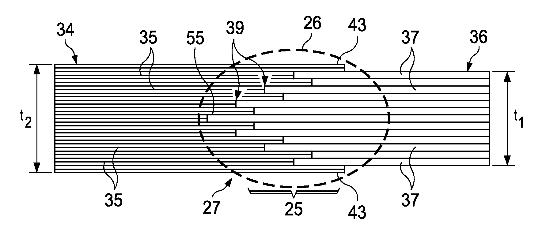
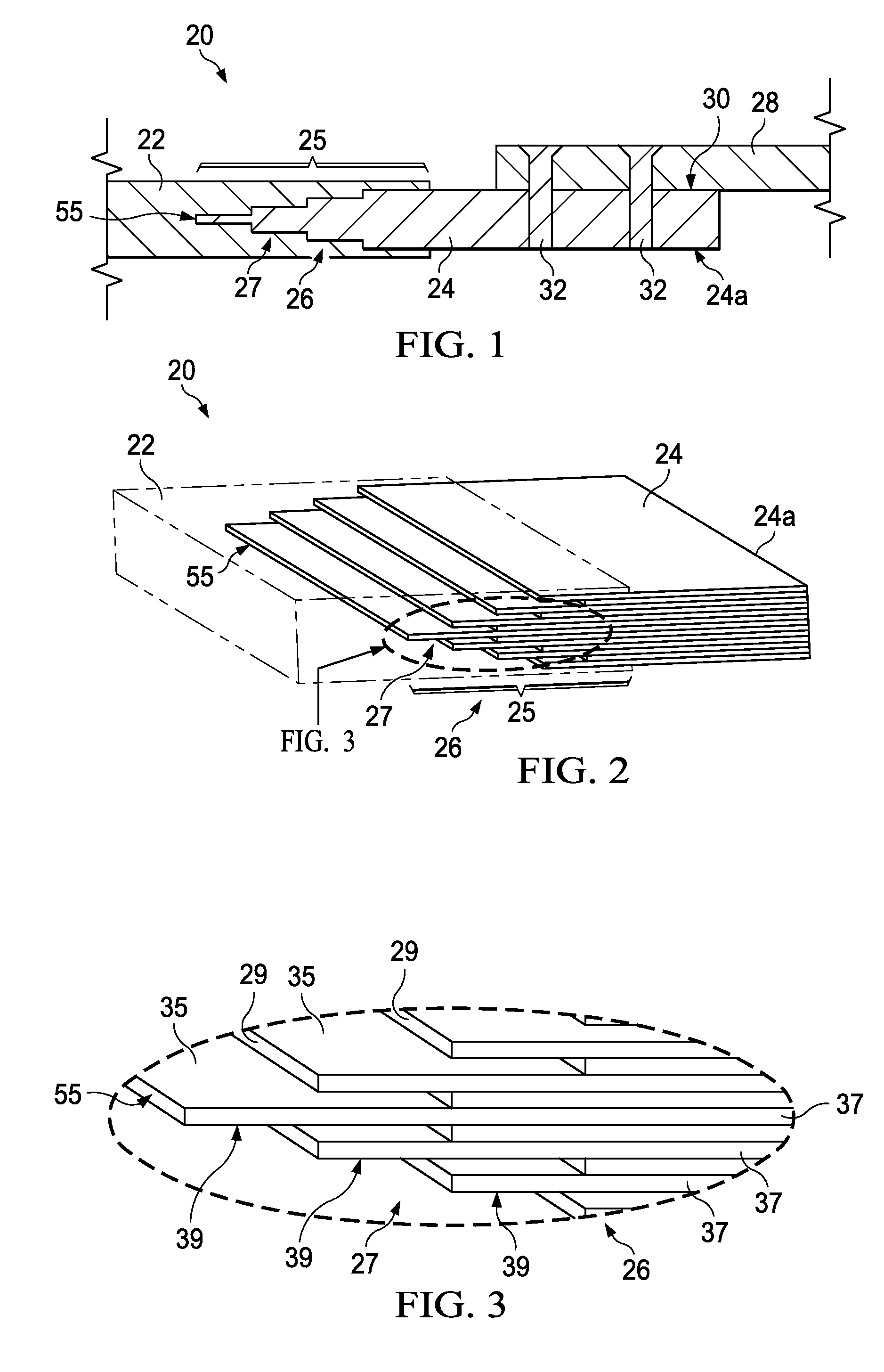
[0052]Referring first to FIG. 1, a hybrid composite structure 20 includes a composite resin portion 22 joined to a metal portion 24 by a transition section 25 that includes a composite-to-metal joint 26. In the illustrated example, the composite structure 20 is a substantially flat composite sheet, however depending upon the application, the structure 20 may have one or more curves, contours or other geometric features. For example, composite structure 20 may comprise an inner and / or outer contoured skin 20 of an aircraft (not shown) which is secured to a frame portion 28 of the aircraft by means of a lap joint 30 and fasteners 32 which pass through the composite structure 20 into the frame portion 28.

[0053]The frame portion 28 may comprise a composite, a metal or other rigid material, and the metal portion 24 of the structure 20 may serve as a rigid metal fitting 24 that is suited to transfer a range of loads and types of loadings between the frame portion 28 and the composite port...


PUM

PropertyMeasurementUnit
thicknessaaaaaaaaaa
thicknessaaaaaaaaaa
thicknessaaaaaaaaaa

Abstract

A composite structure comprises stacked sets of laminated fiber reinforced resin plies and metal sheets. Edges of the resin plies and metal sheets are interleaved to form a composite-to-metal joint connecting the resin plies with the metal sheets.

Description

CROSS REFERENCE TO RELATED APPLICATIONS[0001]This application is a continuation-in-part of U.S. patent application Ser. No. 12 / 857,835 filed Aug. 17, 2010, and issued as U.S. Pat. No. 8,652,606 Feb. 18, 2014, the entire disclosure of which is incorporated by reference herein.BACKGROUND INFORMATION[0002]1. Field[0003]This disclosure generally relates to composite structures, especially fiber reinforced resin laminates, and deals more particularly with a hybrid composite having a composite-to-metal joint, as well as to a bonded metal laminate used in the joint.[0004]2. Background[0005]Bonding techniques are often used to assemble composite structures. In applications where the composite structure also requires fasteners, the local thickness or gauge of the structure surrounding the fastener may need to be increased in order to withstand loads transmitted through the fastener joint. As the local thickness of the structure increases, the fastener may need to be lengthened, thereby addin...

Claims


Application Information

Patent Timeline
Patent Type & Authority Patents(United States)
IPC IPC(8): B32B5/26B32B5/28B29C70/86B29C70/88B29L31/30B32B3/06B32B3/14B32B3/18B32B7/12B32B15/01B32B15/08B32B15/14B64C1/06B64C1/12C22C14/00
CPCB64C1/061B32B5/26B32B5/28B32B7/12B32B15/01B32B15/08B32B15/14B32B3/06B32B3/14B32B3/18B64C1/12C22C14/00B29C70/86B29C70/885B29L2031/3088B29L2031/3082Y02T50/433Y02T50/43B32B2250/05B32B2250/20B32B2260/023B32B2260/046B32B2262/106B32B2305/076B32B2305/77B32B2307/714B32B2605/18B29L2031/3002B29L2031/3079B29C66/1248B29C66/1282B29C66/12861B29C66/24221B29C66/43B29C66/50B29C66/71B29C66/7212B29C66/723B29C66/742B29C65/02B29L2031/3085Y10T156/10Y10T428/12361Y10T428/12347Y10T403/70Y10T428/19Y10T428/12493Y10T428/12007Y10T428/31678Y10T428/195B29C66/721B29C66/14Y02T50/40B29C70/304B29K2307/04B29K2309/08B29K2063/00B29C66/72321B29C65/562B29C65/48B29C66/712B29C65/72B32B37/12B32B37/144B32B37/182
Inventor GRIESS, KENNETH HARLANGEORGESON, GARY E.
Owner THE BOEING CO
Why Eureka
Try Eureka