Ankle-foot orthosis

a technology for ankles and knees, applied in the field of ankle orthosis, can solve the problems of sensitive wear of the supporting portion, and achieve the effects of normal gait, high wear comfort for patients, and high resistance to wear and tear

Inactive Publication Date: 2005-05-03
CAMP SCANDINAVIA
View PDF9 Cites 56 Cited by
  • Summary
  • Abstract
  • Description
  • Claims
  • Application Information

AI Technical Summary

Benefits of technology

[0006]It is an object of the present invention to provide an orthosis with an adequate stiffness, adjusted for people with milder drop foot, which preserves the supporting function. The object is achieved with an ankle-foot orthosis according to the present invention. The orthosis comprises a foot plate, arranged to extend beneath the sole of the foot. It further comprises a strut, arranged to extend from the lateral side of said foot plate over the front of the lower leg and anterior of the lateral ankle. The strut comprises a bifurcation that gives rise to two strut branches, arranged to extend on the lower leg. Also included are a fastening means for fastening the orthosis to the leg. Thus the present invention provides an orthosis with high resistance against wear and tear, high wear comfort for the patient and an orthosis enabling an almost normal gait.

Problems solved by technology

Due to the supporting portion these orthoses provide a strong support but may also be experienced as too rigid by some users, and further the supporting portion is sensitive to wear and tear during walking and may break, especially when used by heavy and very active persons.

Method used


Image

  • Ankle-foot orthosis
  • Ankle-foot orthosis
  • Ankle-foot orthosis

Examples


Embodiment Construction

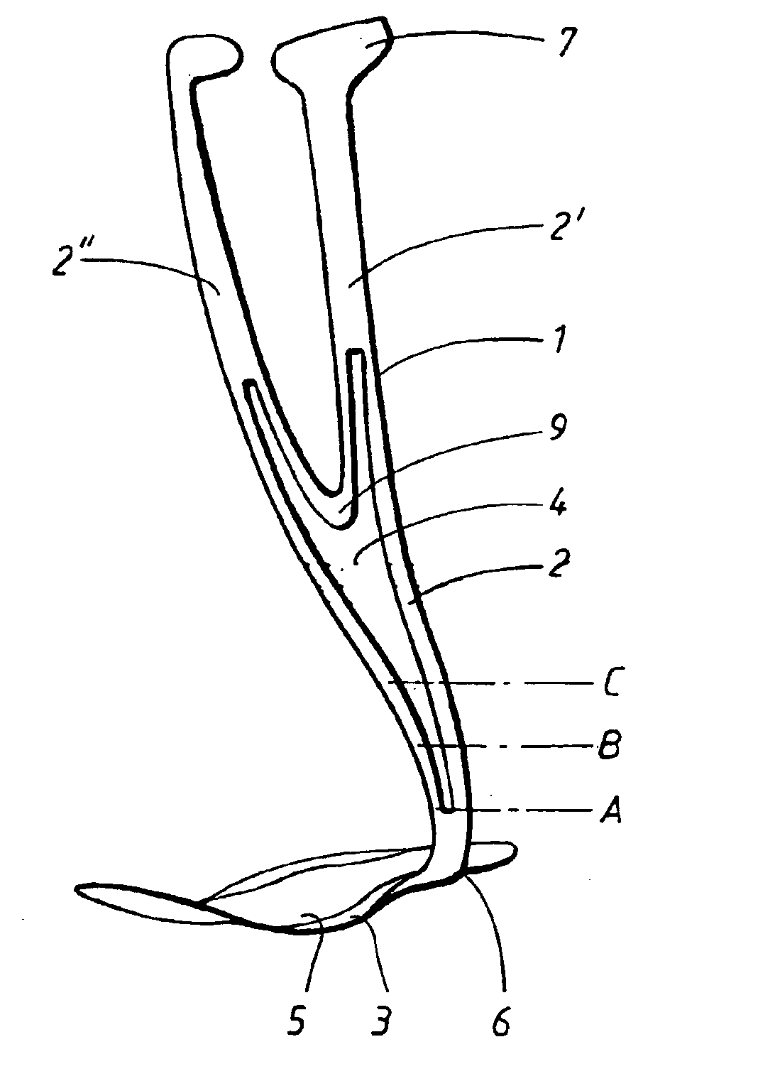
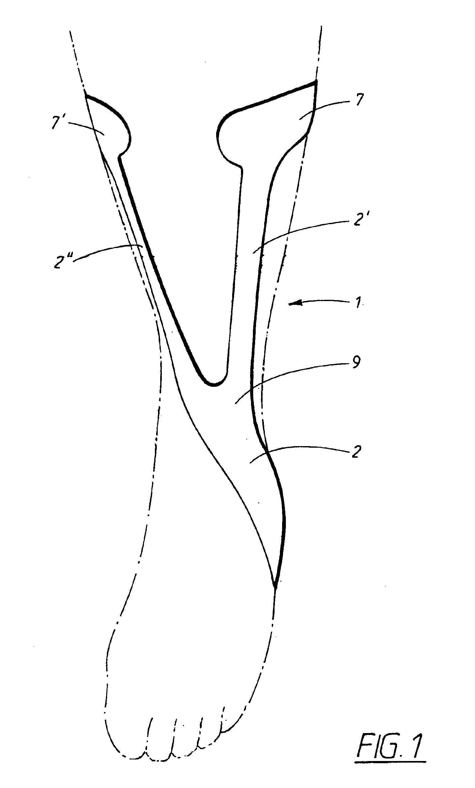
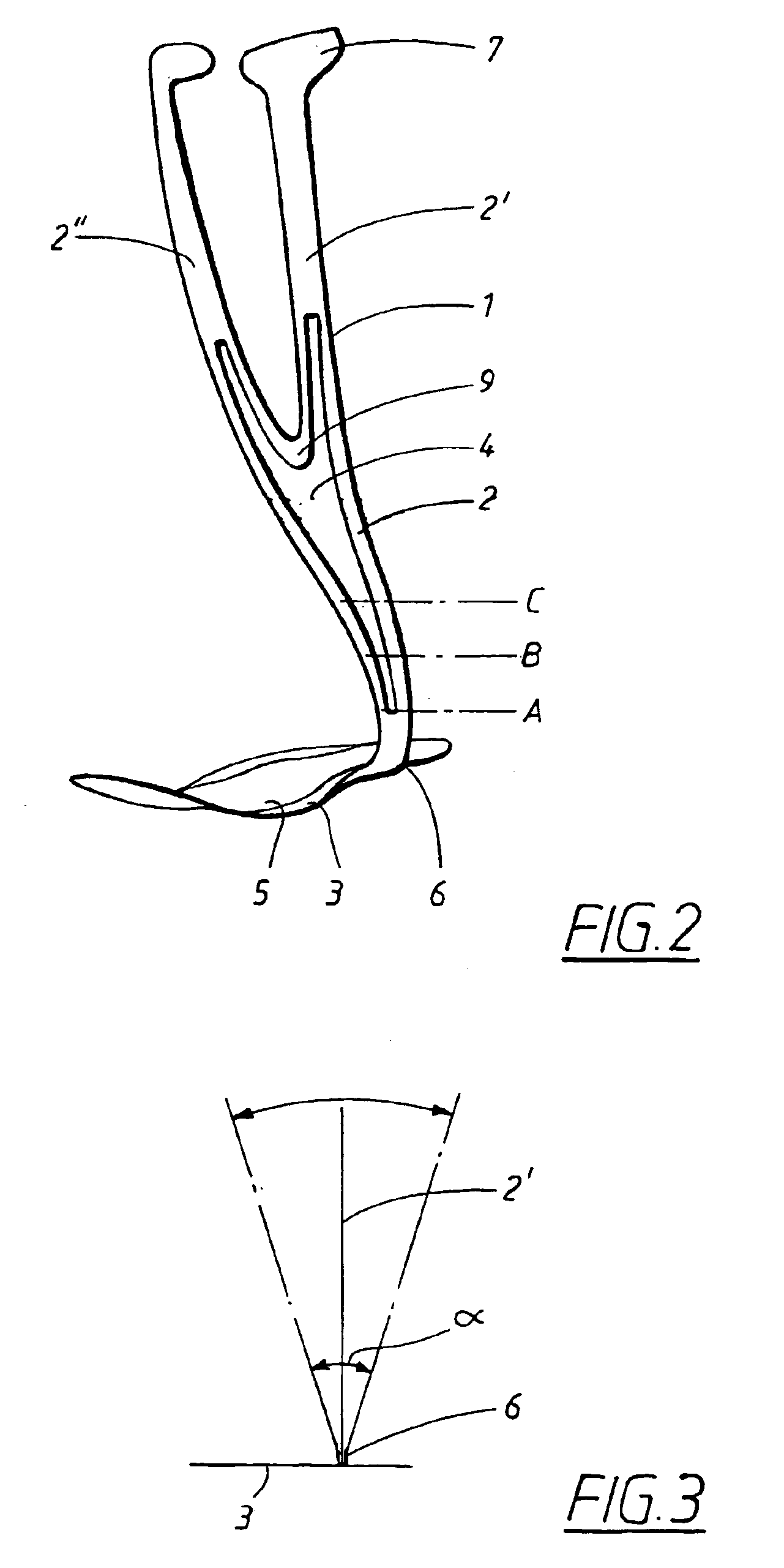
[0014]An ankle-foot orthosis according to the present invention is shown in FIG. 1 and FIG. 2. In the figures, an orthosis 1 for the left foot is shown while it should be understood that a mirror image of the orthosis should be used for the right foot.

[0015]The ankle-foot orthosis 1 comprises a foot plate 3, arranged to be placed under the sole of a patients foot, and a fastening means (not shown), arranged in the upper portion of the orthosis 1 for fastening the orthosis 1 to the lower leg. The fastening means, preferably a strap, and the orthosis 1 are preferably provided with so-called VELCRO or “hook and loop” surfaces providing an easy means of taking on and off the orthosis 1. The strap 61 is preferably strapped on the lower leg having a hook type surface 62, on its first end 62, facing outwards, cf FIG. 6, in the area devised to be applied under the pads 7 of the ortosis 1. The orthosis 1 is then applied over said strap with a loop type surface on the pads 7 facing inwards to...


PUM


Abstract

The present invention provides an ankle-foot orthosis (1) that comprises a strut (2) extending over the front of the lower leg and anterior of the lateral ankle, a foot plate (3) extending beneath the sole of the foot and a fastening means for the fastening the orthosis (1) to the leg. The strut comprises a bifurcation zone (9) and two strut branches (2′, 2″) arranged to extend on the outside of the lower leg on each side of the tibia. Thus the present invention provides an orthosis (1) with high resistance against wear and tear, high wear comfort for the patient and an orthosis (1) enabling an almost normal gait.

Description

FIELD OF THE INVENTION[0001]The present invention relates to an ankle-foot orthosis, particularly for patients suffering from so called drop foot, resulting from paralysis of the anterior muscles of the leg due to e.g. lesions of the peroneal nerve.BACKGROUND OF THE INVENTION[0002]U.S. Pat. No. 5,897,515 discloses an ankle-foot orthosis, comprising a frame of thin flexible material extending over the front of the lower leg, anterior of the lateral ankle and beneath the part of the sole of the foot and a supporting portion of rigid material extending over a narrow part of the front of the lower leg, anterior of the lateral ankle and beneath the part of the sole of the foot. The disclosed orthosis may be worn under the patients ordinary clothes and shoes.[0003]U.S. Pat. No. 2,949,111 discloses a drop-foot brace comprising a supporting sole member to be placed into a shoe and beneath the foot of a handicapped person; a leg embracing member releasably applicable to the leg of said perso...

Claims


Application Information

Patent Timeline
Patent Type & Authority Patents(United States)
IPC IPC(8): A61F5/01A61F5/02
CPCA61F5/0111A61F5/01
Inventor SMITS, JAN F. A.
Owner CAMP SCANDINAVIA
Why Eureka
Try Eureka