Electronic camera having a standby mode for reducing delays in image pickup

a technology of standby mode and camera, which is applied in the field can solve the problems of limited capacity of battery as power source which electrically enables all the operations, weak chances of good pictures of electronic still cameras, etc., and achieve the effect of avoiding wasteful power consumption and sufficiently shortening the release time lag

Inactive Publication Date: 2005-05-03
OLYMPUS CORP
View PDF13 Cites 73 Cited by
  • Summary
  • Abstract
  • Description
  • Claims
  • Application Information

AI Technical Summary

Benefits of technology

[0007]The present invention hence has an object of providing an electronic still camera which avoids wasteful power consumption as much as pos

Problems solved by technology

Electronic still cameras are said to be weak in chances for good pictures because of the long release time lag.
However, in el

Method used


Image

  • Electronic camera having a standby mode for reducing delays in image pickup
  • Electronic camera having a standby mode for reducing delays in image pickup
  • Electronic camera having a standby mode for reducing delays in image pickup

Examples


first embodiment

[0058](First Embodiment)

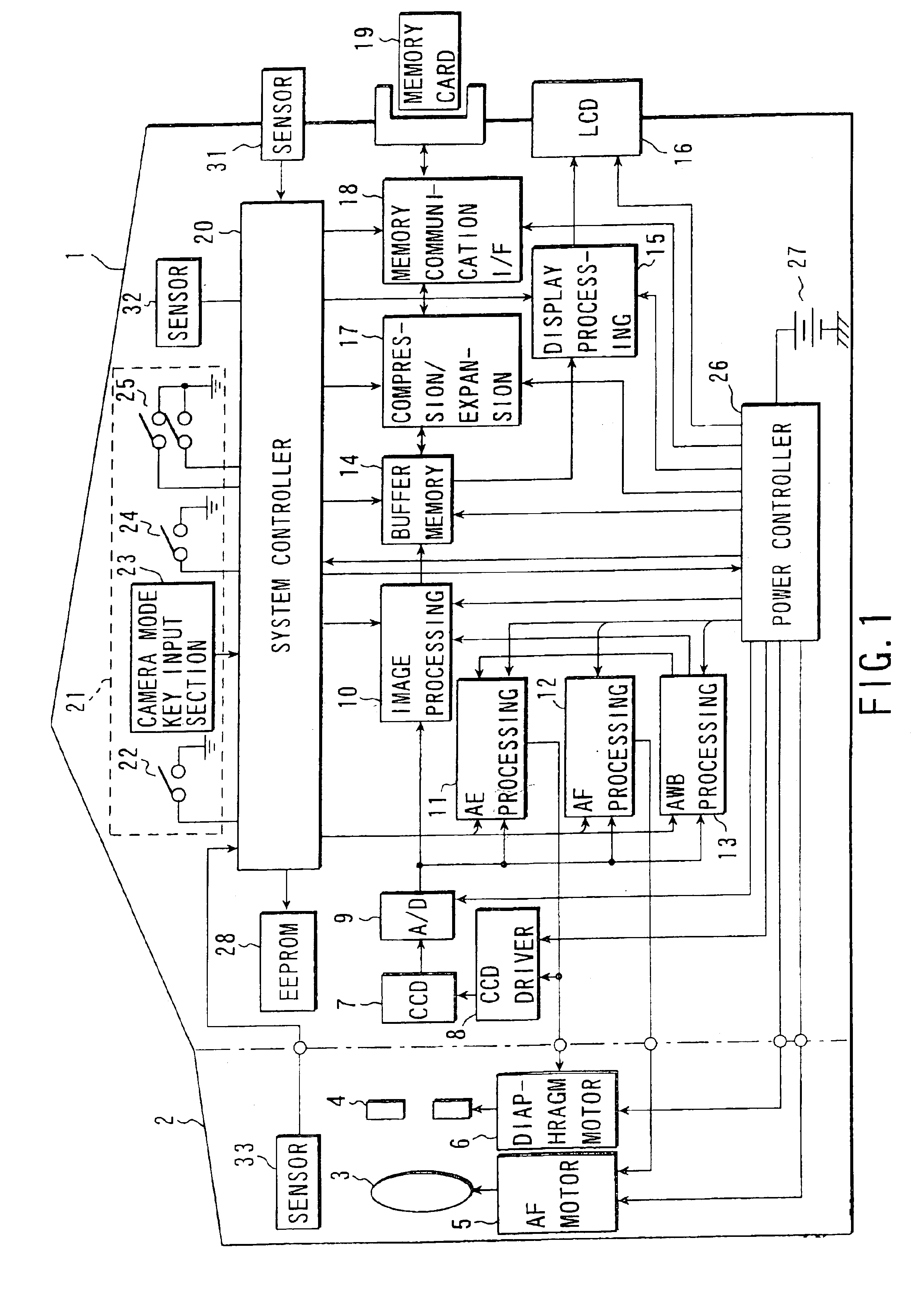
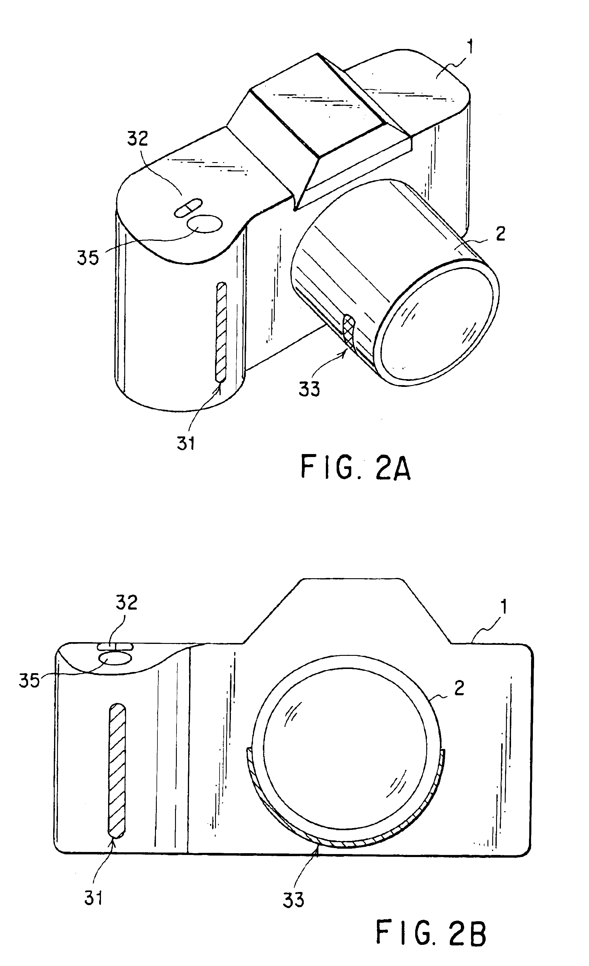
[0059]FIG. 1 is a block diagram showing the structure of an electronic still camera according to a first embodiment of the present invention. FIG. 2A is a perspective view of the electronic still camera according to the first embodiment of the present invention, and FIG. 2B is a front view thereof. This electronic still camera can roughly be divided into a camera body 1 and a lens mirror cylinder 2.

[0060]Object light passes through an image pickup lens 3 provided in the lens mirror cylinder 2 and the light amount is controlled by a diaphragm 4. The image pickup lens 3 is driven by an AF motor 5, and the diaphragm 4 is driven by a diaphragm motor 6. The object light which has passed through the image pickup lens 3 and the diaphragm 4 is introduced into the camera body 1 and enters into a CCD two-dimensional color image sensor (hereinafter referred to simply as a CCD) 7. In this manner, an object image is formed on the image pickup surface of the CCD 7.

[0061]In...

second embodiment

[0102](Second Embodiment)

[0103]FIGS. 4A and 4B show an example of layout of sensors in an electronic still camera according to another embodiment of the present invention. In the present embodiment, the sensor 31 is provided in the front surface side of the grip part of the camera body 1 and a sensor 34 is provided in the side surface side of the of the grip part. Like in the first embodiment, the sensor 32 is provided at the release button part.

[0104]The sensor 34 is thus additionally provided to respond to various ways of holding the camera. For example, when the camera is held longitudinally with the grip part situated lower as shown in FIG. 4B, the sensor 34 securely detects a hand of the user even if the sensor 31 does not detect a hand of the user. Accordingly, in the present embodiment, it is determined that the user has an intention to take a picture and preliminary operations are carried out for taking a picture if at least one of the sensors 31 and 34 is on and if the sens...

third embodiment

[0110](Third Embodiment)

[0111]FIG. 6 shows a layout example of sensors in an electronic still camera according to further another embodiment of the present invention. The present embodiment includes only the sensor 32 provided in the vicinity of the release button 35 and is characterized in that preliminary operations for image pickup are carried out if the power source is set on by the main power switch 22 and if the sensor 32 has detect contact or approach of a hand of a user.

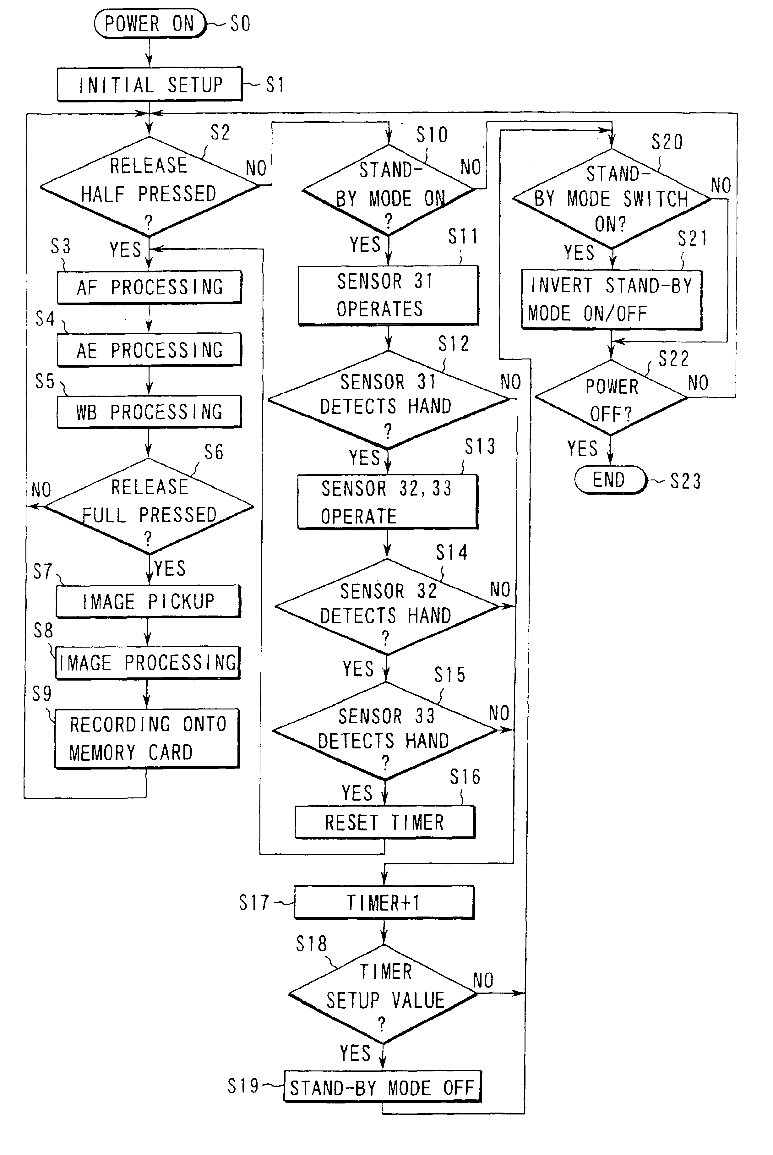
[0112]Next, with reference to the flowchart shown in FIG. 7, explanation will be made of an example of operation for shortening the release time lag in the present embodiment. These operations are released as control by the system controller 20 and processing of the system controller 20 itself.

[0113]The processing steps S0 to S9 in FIG. 7 are the same as those in FIGS. 3 and 5. That is, when the main power switch 22 is pressed down and the power source is turned on (step S0), various initial setups are carrie...


PUM


Abstract

An electronic still camera includes a stand-by mode switch and is capable of setting a stand-by mode in which a power and/or driving pulse is supplied to a CCD so that the mode can immediately shift to an image pickup operation upon a release instruction by a release switch. In the camera, a plurality of sensors for detecting contact or approach of a hand to make an image pickup operation are provided dispersedly at different positions, respectively. If the stand-by mode is set by the stand-by mode switch and all the sensors detect contact or approach of the hand, each processing in an AE processing section, AF processing section, and AWB processing section is carried out as a preliminary operation for image pickup.

Description

CROSS-REFERENCE TO RELATED APPLICATIONS[0001]This application is based upon and claims the benefit of priority from the prior Japanese Patent Applications No. 11-070099, filed Mar. 16, 1999; and No. 2000-062385, filed Mar. 7, 2000, the entire contents of which are incorporated herein by reference.BACKGROUND OF THE INVENTION[0002]The present invention relates to an electronic still camera which picks up images with use of a solid image-pickup device and particularly to an electronic still camera which shortens the release time lag.[0003]Widely spreading now are so-called electronic still cameras in which an object image is formed on, for example, a CCD two-dimensional image sensor by an image pickup optical system and is converted into an electric signal, and the image signal of a still image thus obtained is recorded on a recording medium such as a semiconductor memory or a magnetic disk.[0004]This kind of electronic still camera generally takes a quite longer time from when the pow...

Claims


Application Information

Patent Timeline
IPC IPC(8): G03B7/00G02B7/28G03B13/36G03B19/02H04N5/225H04N5/76H04N5/907H04N5/232H04N5/77H04N9/804H04N101/00
CPCH04N5/232H04N5/23241H04N5/772H04N5/23245H04N9/8042H04N5/907H04N23/673H04N23/651H04N23/667
Inventor ASAKURA, YASUO
Owner OLYMPUS CORP
Why Eureka
Try Eureka