Multilayered structures comprising magnetic nano-oxide layers for current perpindicular to plane GMR heads

a technology of magnetic nano-oxide and perpindicular to plane gmr, which is applied in the field of fabrication of giant magnetoresistive (gmr) magnetic field sensors, can solve the problems of undesirable current shunting, adverse effects on the overall sensitivity of the sensor, and difficulty in fabricating a cpp sensor element having a resistance within reasonable limits for practical applications, and achieves enhanced magnetoresistive properties

Inactive Publication Date: 2005-05-03
HEADWAY TECH INC
View PDF10 Cites 33 Cited by
  • Summary
  • Abstract
  • Description
  • Claims
  • Application Information

AI Technical Summary

Benefits of technology

[0011]It is a further object of this invention to provide such a novel CPP MR read-sensor stack structure that has enhanced magnetoresistive properties.

Problems solved by technology

Unfortunately, GMR sensor configurations typically involve layer stacks comprising layers that are electrically conductive but that play no role in providing resistance variations.
As a result, portions of the current can be shunted through regions that are ineffective in terms of sensor operation and, thereby, the overall sensitivity of the sensor is adversely affected.
One problem with CPP sensor configurations has already been alluded to above, the undesirable shunting of current along the edges of the active sensor region.
Another more general problem of even greater importance is the difficulty of fabricating a CPP sensor element having a resistance within reasonable bounds for practical applications.
In this regard, CPP structures formed of metallic multilayers, such as those cited in the patents above, have too low a resistance, whereas MTJ type configurations, having insulating tunneling layers, have too high a resistance.
Nevertheless, for reading high-density magnetic recordings (above 200 Gbit / in2), the thickness of the sensor is limited by the need to resolve magnetic flux transitions, so it is not possible to increase RA meaningfully by increasing thickness.
Such low resistance is difficult to attain in MTJ structures.
Such a thin layer would introduce the problems of pinholes or general reliability over typical usage periods.

Method used


Image

  • Multilayered structures comprising magnetic nano-oxide layers for current perpindicular to plane GMR heads
  • Multilayered structures comprising magnetic nano-oxide layers for current perpindicular to plane GMR heads
  • Multilayered structures comprising magnetic nano-oxide layers for current perpindicular to plane GMR heads

Examples


first embodiment

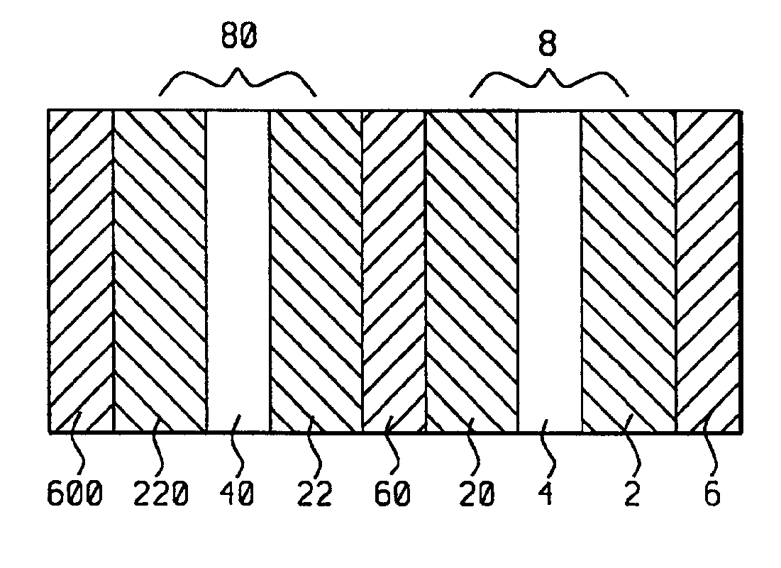
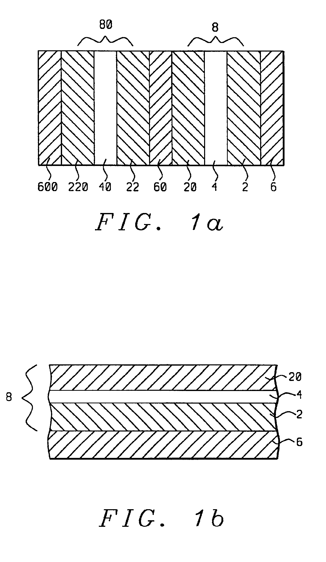
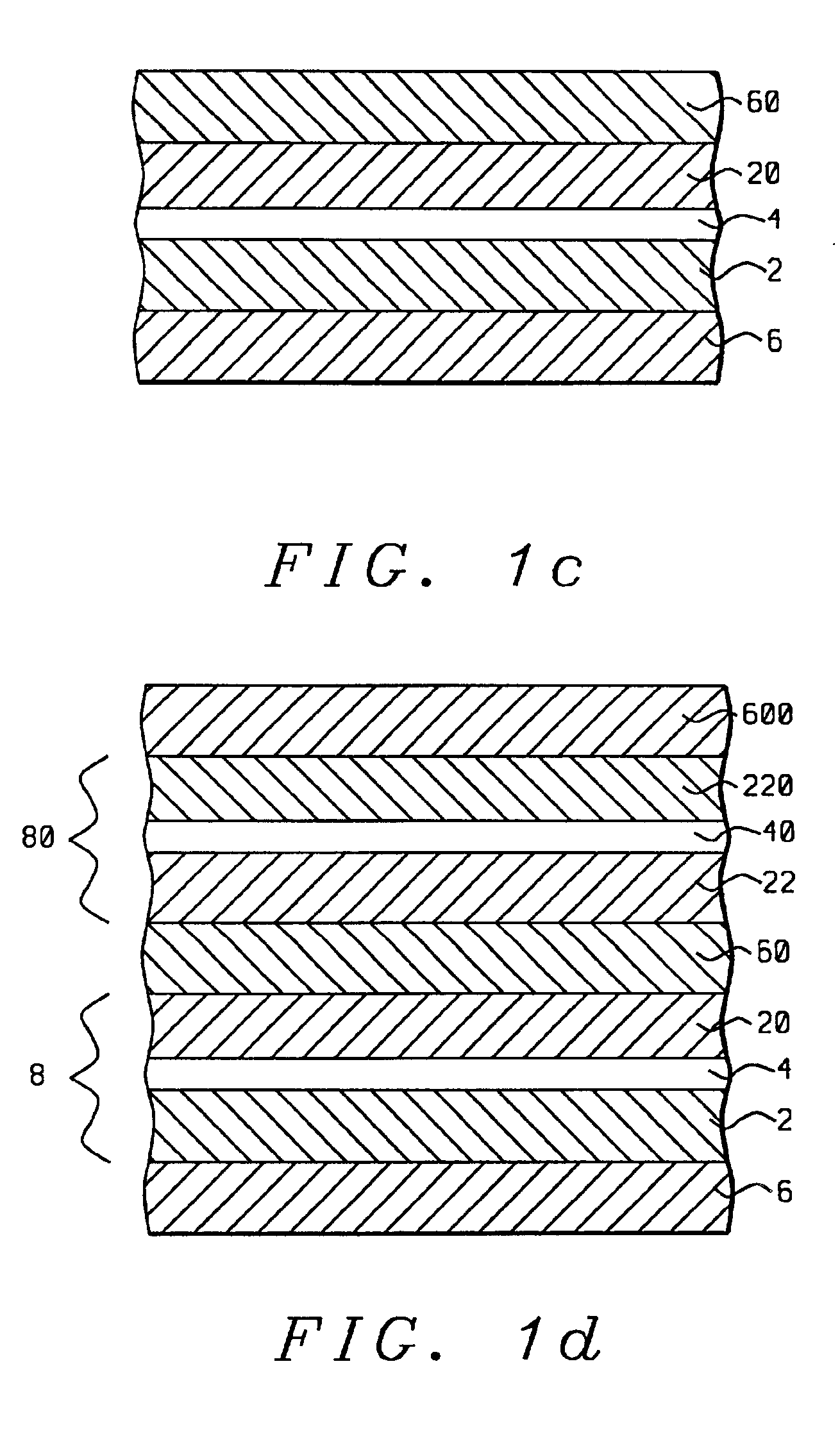
[0024]Referring first to FIG. 1a, there is seen a schematic cross-sectional diagram of a sensor stack formed in accord with the methods and objects of the present invention and wherein magnetic nano-oxide layers (4) and (40) are inserted between ferromagnetic layers (2), (20), (22) and (220) to form two magnetic tri-layers (8) and (80). Non-magnetic spacer layers (6), (60) and (600) separate the magnetic layers from each other and from upper and lower substrates (not shown).

[0025]Referring next to FIG. 1b, there is shown a schematic cross-sectional diagram of an initial step in the formation of the sensor stack of FIG. 1a. There is first formed on an appropriate substrate (not shown) a first metallic, non-magnetic spacer layer (6). All metallic, non-magnetic spacer layers formed in this embodiment and in the embodiments to be described in FIGS. 2, 3, 4, and 5, can be layers of material such as Cu, Au or Ag and can be formed to a thickness of between 0.5 nm and 10 nm. Upon the spacer...

second embodiment

[0029]Referring now to FIG. 2a, there is shown a schematic cross-sectional representation of a sensor stack formed in accord with the present invention. The stack of this embodiment is a CPP stack that differs structurally from that of FIG. 1a by the positioning of the its magnetic nano-oxide layers (10) and (100), which are now at the interfaces of the ferromagnetic layers (9) and (90) (rather than within the body of the ferromagnetic layer) and separated by a non-magnetic metallic spacer layer (12). The dimensions and material compositions of the layers will be discussed below in the context of their formations. It should be noted that the thickness of each ferromagnetic layer (9) and (90) is preferably equal to the sum of the thicknesses of the two ferromagnetic layers (2) and (20) and (22) and (220), in FIG. 1a.

[0030]The performance characteristics of this stack exceed those of the stack in FIG. 1a for the following reason. In order to obtain a large GMR amplitude, it is import...

third embodiment

[0036]Referring next to FIG. 3a, there is shown the present invention, a stack configuration in which one of the ferromagnetic layers (16) is exchange biased (pinned) by an antiferromagnetic layer (15). In this case the antiferromagnetic layer would be a layer of antiferromagnetic material chosen from the group consisting of MnPt, NiMn, IrMn, CrMnPt and MnPtPd, and deposited to a thickness of between 5 nm and 30 nm. The magnetization of the remaining ferromagnetic layer (160) is free to move; thus, layer (160) is a ferromagnetically free layer.

[0037]In prior art CPP spin-valves structures it has been observed that the use of an antiferromagnetic pinning layer leads to a decrease of GMR amplitude. This is not the case in the present embodiment, however, since the resistance is dominated by the magnetic nano-oxide layers. Adding the resistance of an antiferromagnetic layer in series is not going to affect the resistance appreciably. This structure, therefore, comprises only one soft l...


PUM

PropertyMeasurementUnit
thicknessaaaaaaaaaa
thicknessaaaaaaaaaa
thicknessaaaaaaaaaa

Abstract

Nano-oxide based current-perpendicular-to-plane (CPP) magnetoresistive (MR) sensor stacks are provided, together with methods for forming such stacks. Such stacks have increased resistance and enhanced magnetoresistive properties relative to CPP stacks made entirely of metallic layers. Said enhanced properties are provided by the insertion of magnetic nano-oxide layers between ferromagnetic layers and non-magnetic spacer layers, whereby said nano-oxide layers increase resistance and exhibit spin filtering properties. CPP sensor stacks of various types are provided, all having nano-oxide layers formed therein, including the spin-valve type and the synthetic antiferromagnetic pinned layer spin-valve type. Said stacks can also be formed upon each other to provide laminated stacks of different types.

Description

BACKGROUND OF THE INVENTION[0001]1. Field of the Invention[0002]This invention relates generally to the fabrication of giant magnetoresistive (GMR) magnetic field sensors of a “current-perpendicular-to-the-plane” (CPP) configuration and more particularly to such sensors having novel multilayer structures that incorporate magnetic nano-oxide layers.[0003]2. Description of the Related Art[0004]Magnetic read sensors that utilize the giant magnetoresistive (GMR) effect for their operation are generally of the “current-in-the-plane” (CIP) configuration, wherein current is fed into the structure by leads that are laterally disposed to either side of the active sensor region and moves through the structure essentially within the planes of its magnetic layers. Since the operation of GMR sensors depends on resistance variations of the active magnetic layers caused by changes in the relative directions of their magnetic moments, it is important that a substantial portion of the current pass t...

Claims


Application Information

Patent Timeline
Patent Type & Authority Patents(United States)
IPC IPC(8): G01R33/06G01R33/09G11B5/39H01F10/16H01F10/32H01F41/14H01L43/08H01L43/10H01L43/12
CPCB82Y10/00B82Y25/00B82Y40/00G01R33/093G11B5/3903H01F10/3259G11B5/3967H01F10/3272H01F41/302G11B5/3909G11B2005/3996
Inventor DIENY, BERNARDHORNG, CHENGJU, KOCHANLI, MINLIAO, SIMON
Owner HEADWAY TECH INC
Why Eureka
Try Eureka