Cutter blade position detection mechanism and method of reporting cutter malfunction

a technology of position detection mechanism and cutter blade, which is applied in the direction of manufacturing tools, printing, metal-working machine components, etc., can solve the problems of printer failure, loss of time and possibly sales for the operator of the printer, and jamming of paper in the devi

Inactive Publication Date: 2005-05-10
TOSHIBA GLOBAL COMMERCE SOLUTIONS HLDG
View PDF34 Cites 104 Cited by
  • Summary
  • Abstract
  • Description
  • Claims
  • Application Information

AI Technical Summary

Problems solved by technology

However, these cutter position devices do not indicate to an operator where in the cutting cycle the blades may not be closing or opening properly to allow an operator to accurately identify and correct malfunctions.
Various malfunctions may occur in the cutting process resulting in failure to cut, failure to completely cut material, and resulting in jamming of paper in the device.
These failures can cause printer failure and loss of time and possibly sales for an operator of the printer.
When the printer fails customers are forced to wait often resulting in loss of sales for the operator.
Heretofore the printer operators only know when the cutters fail due to the fact that they have to manually cut the receipt from the pap

Method used


Image

  • Cutter blade position detection mechanism and method of reporting cutter malfunction
  • Cutter blade position detection mechanism and method of reporting cutter malfunction
  • Cutter blade position detection mechanism and method of reporting cutter malfunction

Examples


Embodiment Construction

[0022]Refer now to the drawings wherein depicted elements are not necessarily shown to scale and wherein like or similar elements are designated by the same reference numeral through the several views.

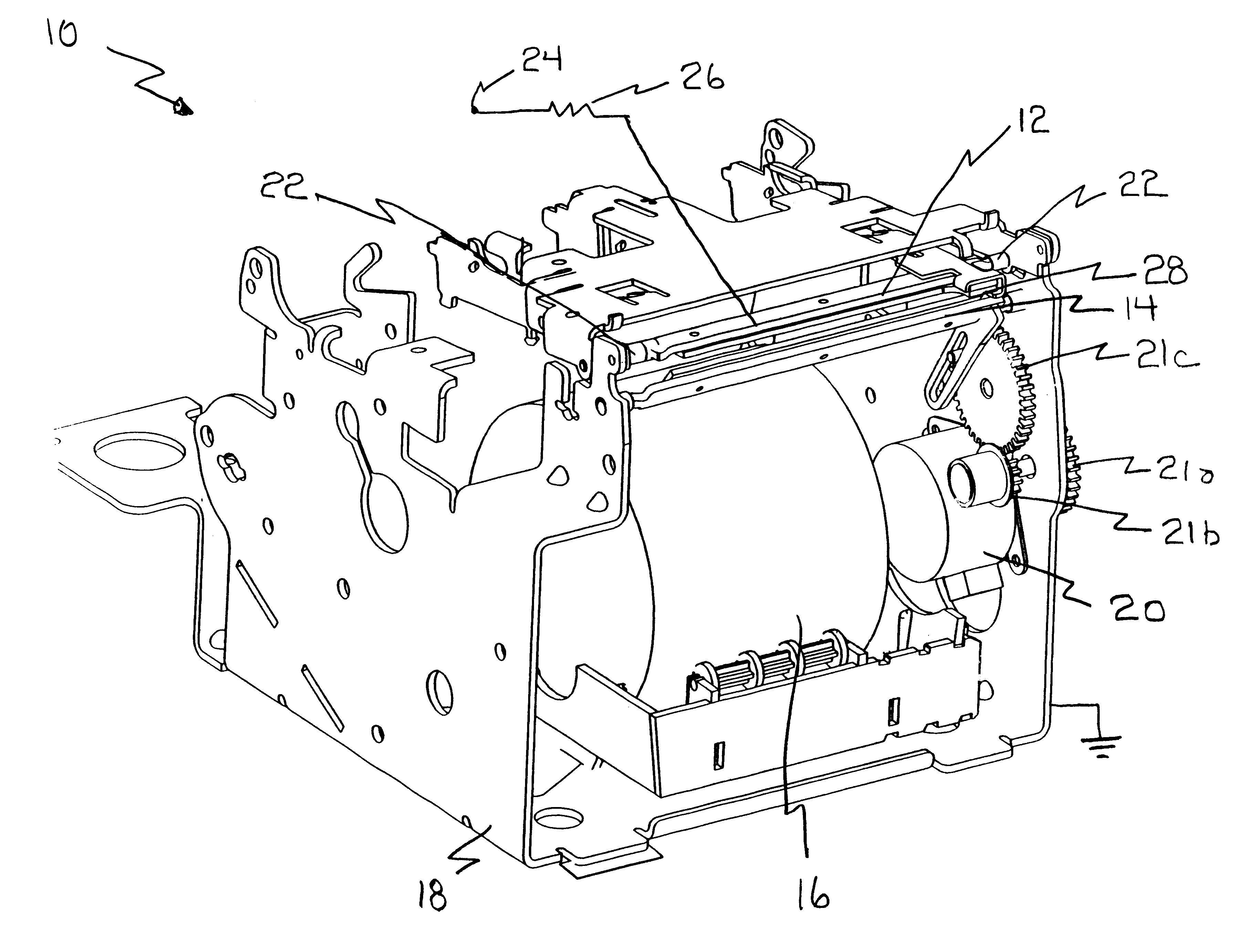
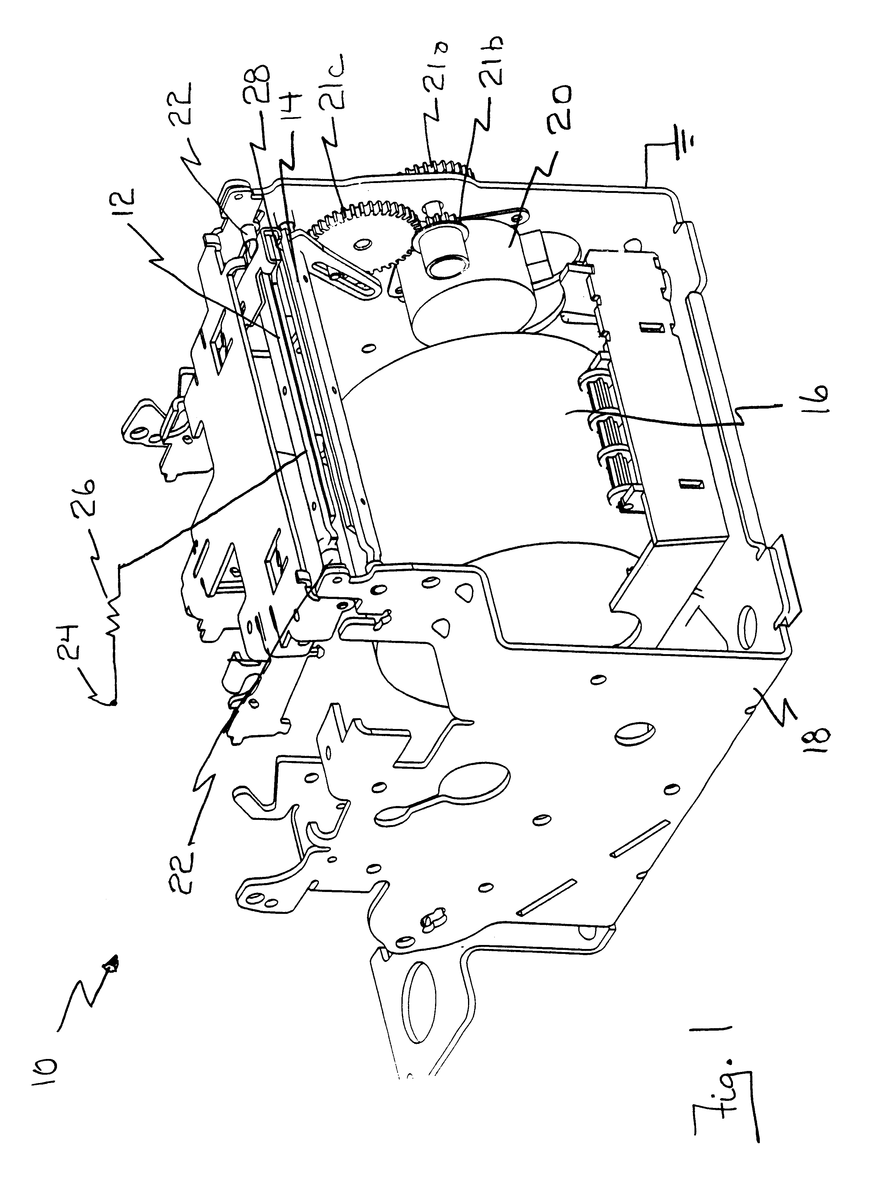
[0023]FIG. 1 is a perspective view of a continuous paper roll printing device 10, with the cover removed, utilizing cutter blades 12 and 14 as a cutter blade position detection switch. Printer 10 includes a continuous roll of paper 16, first blade 12, second blade 14, printer frame 18, and stepper motor 20.

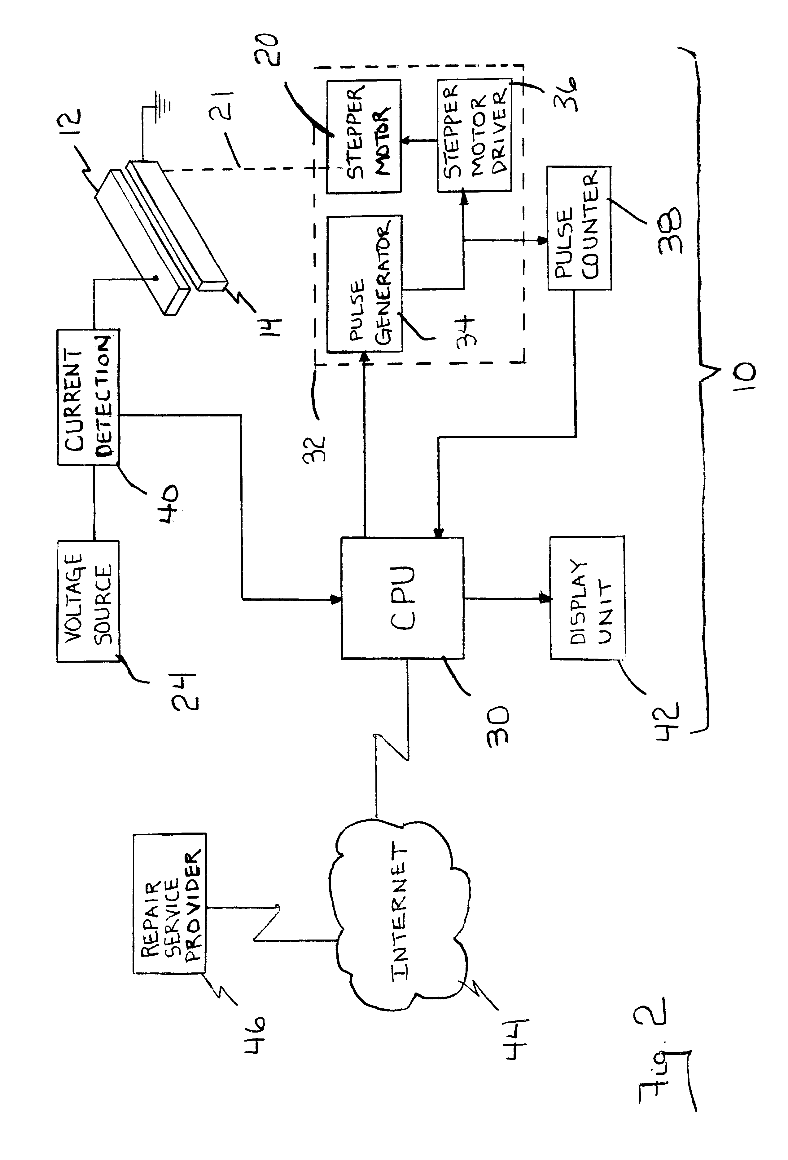
[0024]As shown in FIG. 1, first blade 12 is a stationary blade and second blade 14 is a shear blade, each constructed of an electrically conductive material. In this embodiment, cutter blade 12 is connected to frame 18 with non-conductive bushings 22. Blade 14 is movably connected to frame 18 which is ground. A power source 24, such as but not limited to a DC source, is connected to first blade 12. A resistor 26 may be connected between power source 24 and blade 12. A non-conductive ...


PUM

PropertyMeasurementUnit
Electrical currentaaaaaaaaaa

Abstract

A sheet cutting device utilizing cutter blades as a position detection mechanism and a method of reporting cutter malfunctions is provided. The sheet cutting device including a cutter having a pair of cutter blades, one of the blades connected to a cutter driving mechanism for moving the blade through a cutting cycle, a power source is connected to one of the blades so that a circuit is closed when the blades contact one another, and a current sensing device in connection with the circuit to identify when the blades are in physical contact.

Description

TECHNICAL FIELD[0001]The present invention relates in general to utilizing cutter blades in a printer for identifying the position of the blades and for reporting cutter failures; and in particular, to utilizing cutter blades as an electrical switch to indicate when the cutting blades are in the fully open position and operating properly or malfunctioning and to a method of reporting the malfunction.BACKGROUND INFORMATION[0002]Many devices such as facsimiles and printers utilize continuous rolls of paper which require cutters. Some of these devices have a separate monitoring device to indicate when the blades are fully open and paper may be fed through the cutters. However, these cutter position devices do not indicate to an operator where in the cutting cycle the blades may not be closing or opening properly to allow an operator to accurately identify and correct malfunctions.[0003]Various malfunctions may occur in the cutting process resulting in failure to cut, failure to complet...

Claims


Application Information

Patent Timeline
IPC IPC(8): B41J11/70B26D7/22B26D7/24B26D5/00B26D7/00
CPCB26D5/00B26D7/22B41J11/70B26D7/24Y10S83/942Y10T83/85Y10T83/18Y10T83/088Y10T83/141Y10T83/175
Inventor HARRIS, RICHARD HUNTERTHOMAS, JEFF DAVIDYODER, ROBERT DEAN
Owner TOSHIBA GLOBAL COMMERCE SOLUTIONS HLDG
Why Eureka
Try Eureka