Method and apparatus for installing control lines in a well

a technology for installing control lines and wells, which is applied in the direction of drilling pipes, well accessories, drilling casings, etc., can solve the problems of damage to control lines, loss or impairment of surface control of downhole devices, and damage to control lines secured to pipe strings, so as to prevent impairment of escape routes and improve rig safety

Inactive Publication Date: 2005-05-10
FRANKS INT
View PDF20 Cites 53 Cited by
  • Summary
  • Abstract
  • Description
  • Claims
  • Application Information

AI Technical Summary

Benefits of technology

[0013]The method and apparatus of the present invention allows one or more control lines to be secured along the length of a pipe string as the pipe string is being made up and run into a well. The method and apparatus of the present invention allows control lines to be secured to a pipe string above the rig floor and below the spider, but eliminates the need for an elevated work platform strong enough to support the enormous weight of the pipe string. The method and apparatus of the present invention improves rig safety by preventing impairment of escape routes on the rig floor.
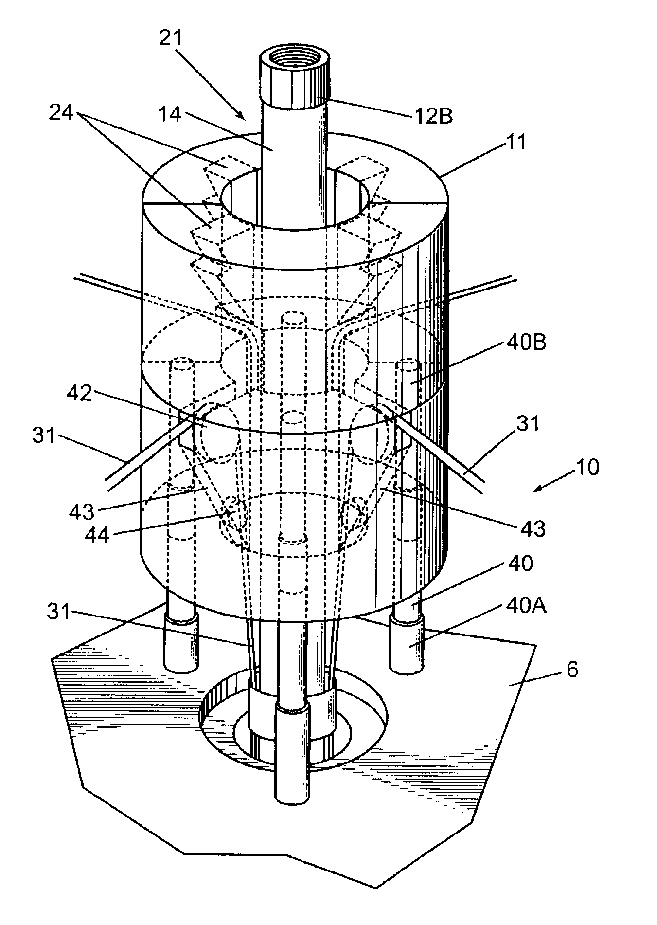
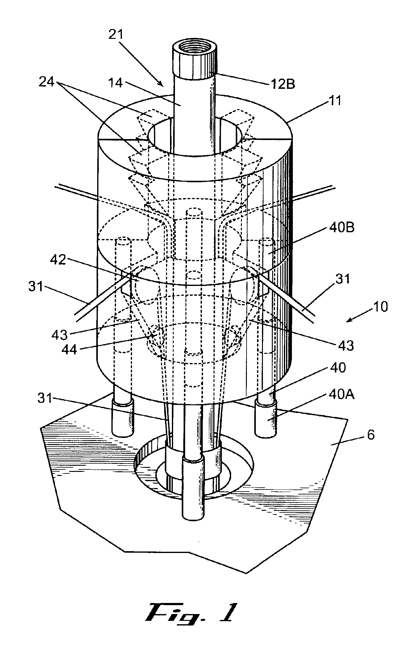
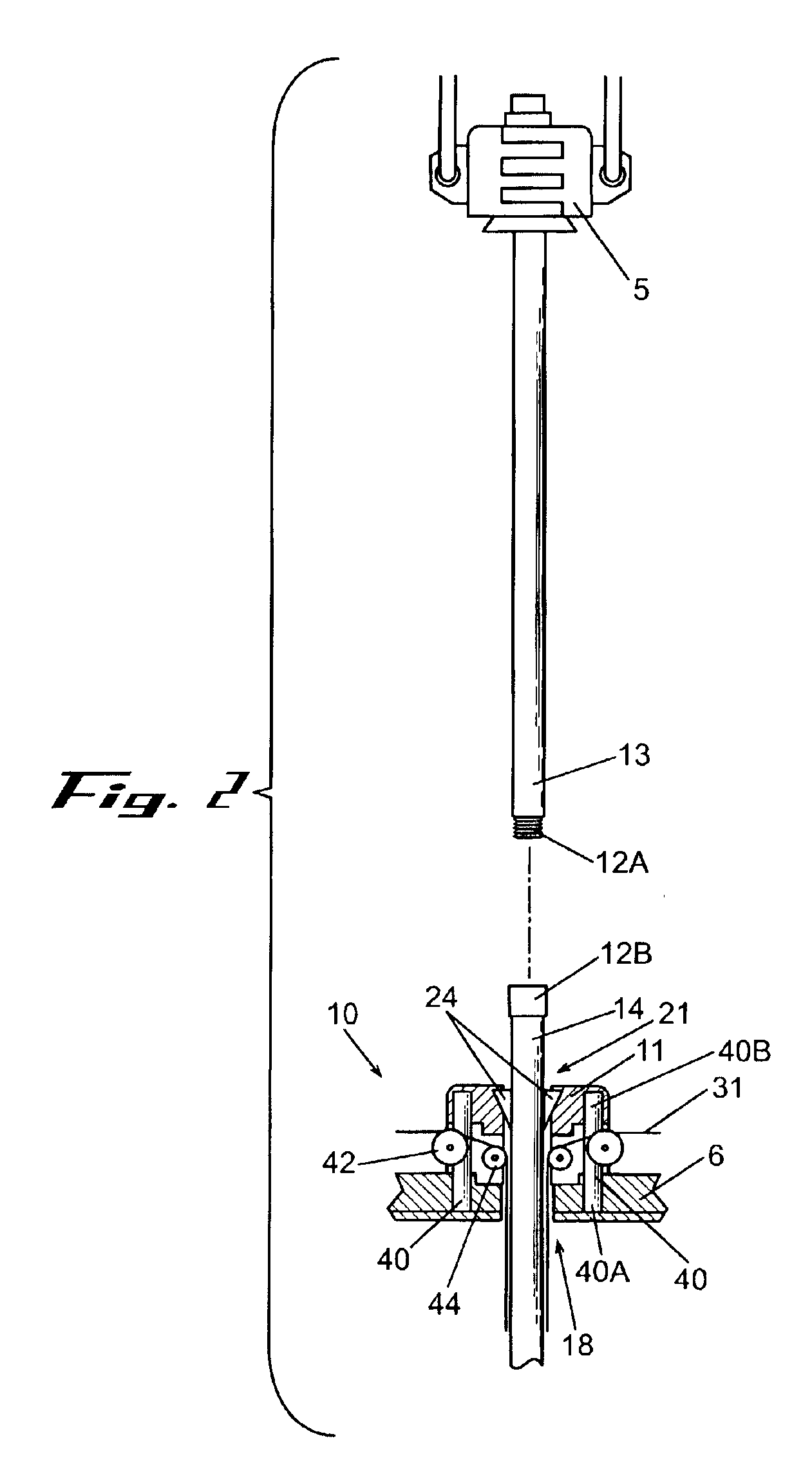
[0014]In the method and apparatus of the present invention, the spider is received within and supportable by a vertically reciprocating retainer. The retainer is adapted to distribute the load on the spider to structural components in or under the rig floor when the pipe string is supported by the spider, and to vertically displace and support the spider when the spider is disengaged from the pipe string and the weight of the pipe string is supported by the elevator. The disengaged spider may be controllably elevated using the retainer to support the spider at a distance above the rig floor to permit rig personnel access to the outer surface of the portion of the pipe string located below the elevated spider and above the rig floor. Access to the outer portion of the pipe string below the spider and above the rig floor permits rig personnel to install fasteners to secure control lines to the pipe string.

Problems solved by technology

Control lines secured to pipe string are subject to being damaged and useless if pinched or crushed, by pipe slips used to grip and support the pipe string while it is being made up and run into the well.
If a control line becomes pinched or trapped between the pipe slips of the spider and the outer surface of the pipe string, or if a control line is pinched between adjacent segments of the pipe slips as they move radially inwardly to contact the pipe string, the control line may be damaged and surface control of downhole devices may be lost or impaired.
However, this method is unsatisfactory for applications requiring multiple control lines being unspooled and fed from more than one location adjacent to the spider where the control lines are more stiff or otherwise resistant to being redirected and positioned using positioning arms and guides.
Also, the gap or recess formed in the radially outwardly disposed portion of the pipe slips is of limited size and is insufficient to accommodate multiple control lines required for controlling multiple downhole devices.
The problem with the method and apparatus for installing control lines described in the '664 Patent is that the work platform must be extremely structurally robust to support the enormous weight of the entire pipe string, the control line, the spider, and the rig personnel making up the pipe string.
The erection of the work platform consumes a large amount of rig time during which no progress is made in completing the well.
After the control lines and pipe string are run into the well, the work platform must be removed from the rig floor, thus consuming additional rig time.
Another problem with the method and apparatus disclosed in the '664 Patent is that rig personnel working on the elevated work platform are dangerously impaired from escaping well blowout or other a well control situation.

Method used


Image

  • Method and apparatus for installing control lines in a well
  • Method and apparatus for installing control lines in a well
  • Method and apparatus for installing control lines in a well

Examples


Embodiment Construction

[0023]Wells are generally drilled deep into the earth's crust to establish fluid communication between the surface and sub-surface geologic formations containing naturally occurring hydrocarbon deposits, such as oil or gas. A well provides a fluid conduit allowing subsurface deposits of oil and gas to be produced at the surface. It is common for a drilled borehole to penetrate a plurality of formations. Formations may contain hydrocarbons or other fluids of different compositions and at different pressures than the hydrocarbons and fluids contained in other formations. Formations may also contain water (aquifers), brine, hydrogen sulfide gas and other materials that may be undesirable.

[0024]A drilled borehole is completed into a well by circulating cement into the annulus between the wall of the drilled borehole and the outer surface of a pipe string called casing to form a cement liner. The cement hardens to isolate penetrated formations from flowing into the well and to the surfac...


PUM


Abstract

A method and apparatus are provided for installing control lines and pipe into a well. The pipe-holding spider that is normally mounted on the rig floor is supportably retained in a vertically movable retainer. The retainer is adapted for controllably elevating the spider above the rig floor when the pipe slips within the spider are not engaged with the outer surface of the pipe string, thereby providing personnel access to a portion of the length of the pipe string below the elevated spider and above the rig floor. Personnel are provided with access to the pipe string for applying a fastener to secure the control line to the pipe string.

Description

BACKGROUND OF THE INVENTION[0001]1. Field of the Invention[0002]The present invention relates to a method and apparatus for installing pipe and control line in a well. More specifically, the present invention relates to a method and apparatus for installing control lines secured to a string of pipe as the pipe is being made up and run into a well.[0003]2. Background of the Related Art[0004]Oil and gas wells may be equipped with control lines for electrically, hydraulically or optically linking various downhole devices to the surface. Control lines may be used to receive data from downhole instruments and to selectively operate from the surface downhole devices such as valves, switches, sensors, relays or other devices. One use of control lines is to open, close or adjust downhole valves in order to selectively produce or isolate formations at locations deep in the well. A control line may transmit downhole data to the surface and communicate commands to the same or other downhole de...

Claims


Application Information

Patent Timeline
Patent Type & Authority Patents(United States)
IPC IPC(8): E21B19/10E21B19/00
CPCE21B19/22E21B19/10
Inventor BUYTAERT, JEANSPADONI, LUCIANOSINCLAIR, EDWARD
Owner FRANKS INT
Why Eureka
Try Eureka