Card connector reduced in operating force

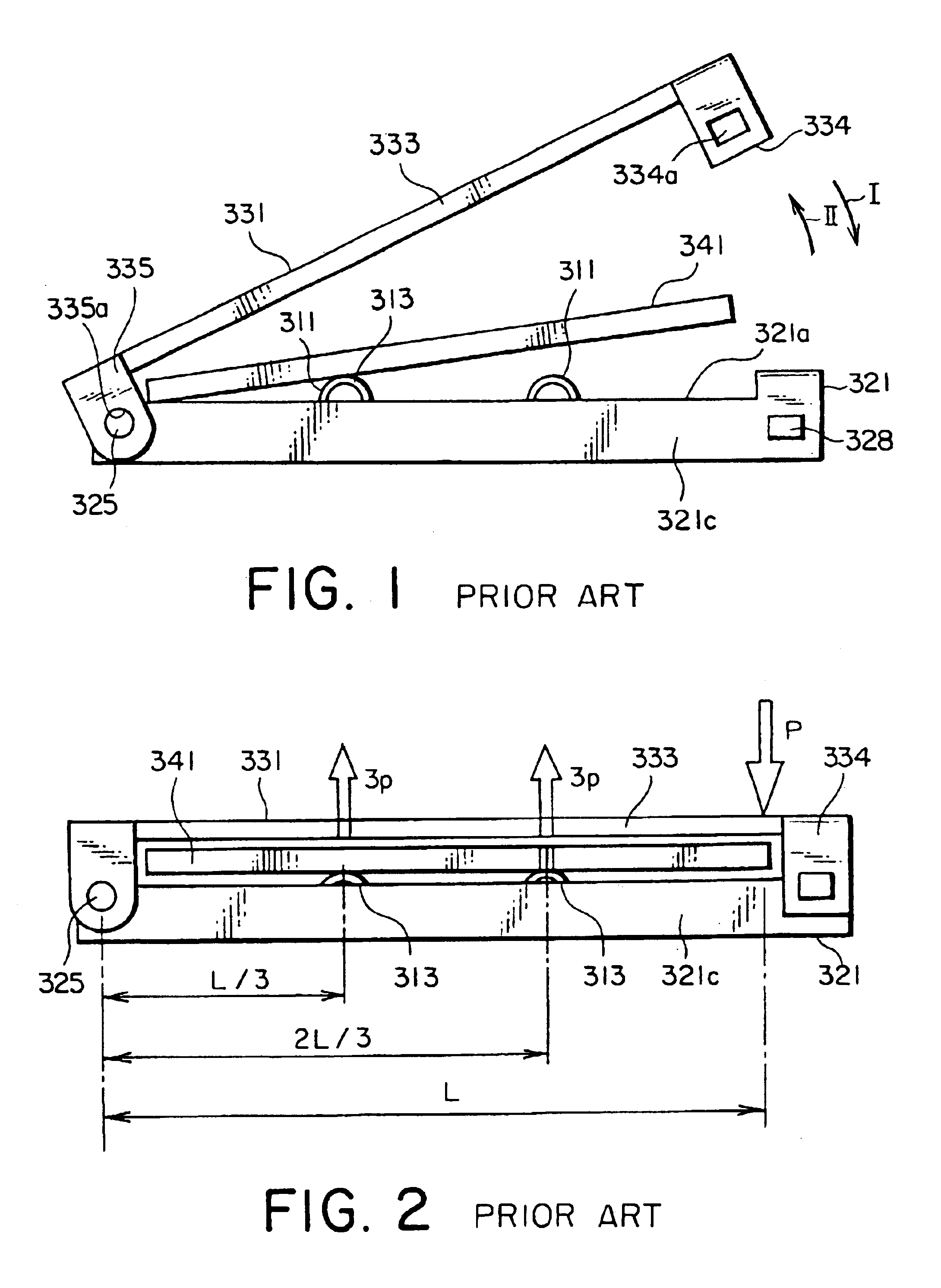
a technology of operating force and operating force, applied in the direction of coupling device connection, weaving, instruments, etc., can solve the problems of unintentional drop off of card 341 from the connector, difficulty in reducing operating force, damage, etc., and achieve the effect of reducing operating for

Inactive Publication Date: 2005-05-10
JAPAN AVIATION ELECTRONICS IND LTD
View PDF12 Cites 55 Cited by
  • Summary
  • Abstract
  • Description
  • Claims
  • Application Information

AI Technical Summary

Benefits of technology

[0012]It is therefore an object of the present invention to provide a card connector which is capable of considerably reducing operating force.

Problems solved by technology

However, it is difficult to considerably reduce the operating force P.
Furthermore, the card 341 may unintentionally be dropped off from the connector and damaged.

Method used


Image

  • Card connector reduced in operating force
  • Card connector reduced in operating force
  • Card connector reduced in operating force

Examples


first embodiment

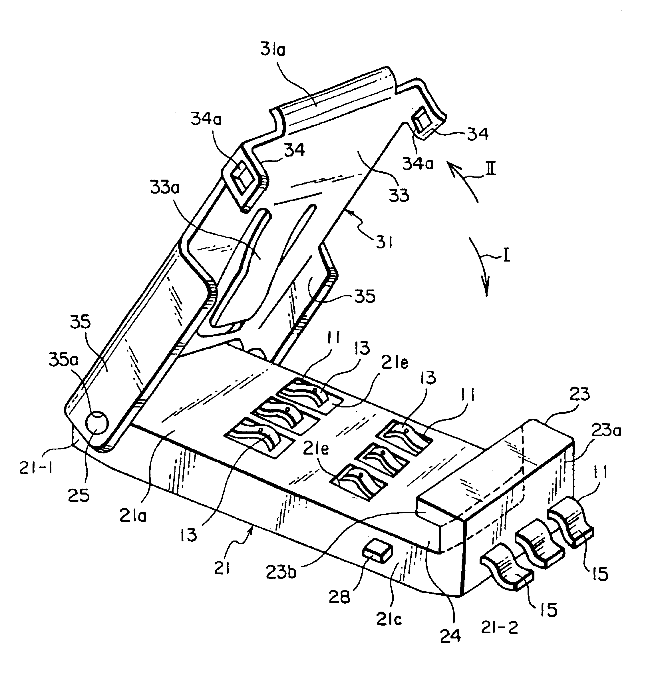
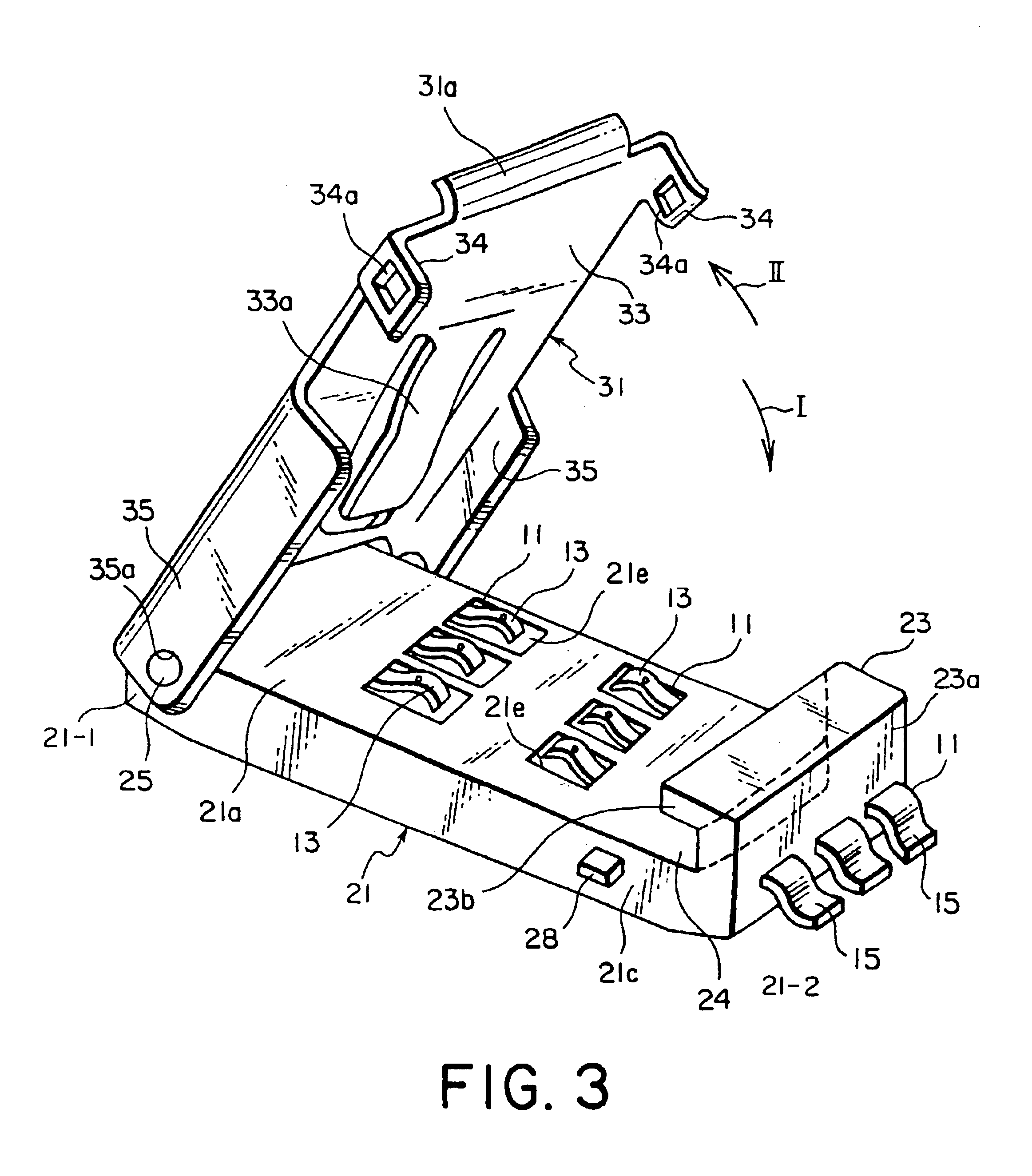
[0025]Referring to FIGS. 3 to 6, description will be made of a card connector according to this invention.

[0026]The connector illustrated in the figures is for use in connecting a small-sized card 41, such as a SIM card which is a module for identifying a subscriber such as a telephone subscriber. The connector comprises six conductive contacts 11, a resin insulator 21 having a generally rectangular shape and holding the contacts 11, and a resin or metal cover 31 pivotally supported at a first end 21-1 of the insulator 21. The insulator 21 has an upper or a principal surface 21a extending between the first end 21-1 and a second end 21-2 opposite to the first end 21-1.

[0027]Each of the contacts 11 has a leaf-spring contacting portion 13 protruding on the principal surface 21a of the insulator 21, and a terminal portion 15 connected to the contacting portion 13 and extending outward from the insulator 21. The contacting portion 13 has elasticity and is located at a position correspond...

second embodiment

[0043]Referring to FIGS. 8 to 10, description will be made of a card connector according to this invention. Similar parts are designated by like reference numerals and description thereof will be omitted.

[0044]The connector illustrated in the figures is for use in connection of the card 41, such as the SIM card. In the connector, the cover 31 has a cover principal plate portion 133 of a flat shape and a pair of side plate portions 135 coupled to the cover principal plate portion 133. The cover principal plate portion 133 is a part covering the upper surface of the card 41 when the cover 31 is closed. The side plate portions 135 are faced to the side surfaces 21c of the insulator 21, respectively. Each of the side plate portions 135 is provided with a pivot portion 135a formed by a circular hole. By fitting the pivot portions 135a to the support shaft portions 25 of the insulator 21, the cover 31 is supported to be rotatable around the support shaft portions 25 in the closing directi...


PUM


Abstract

In a connector including an insulator (21), a conductive contact (11) held by the insulator, and a cover (31) openable and closable for bring the card into press contact with the contact, the insulator has a holding portion (21) formed at its one end to hold one end portion of the card. On the other hand, the cover has an acting portion (33, 33a) to be engaged with the other end portion of the card to press the card towards the contact when the cover is closed. The card is mounted so as to face a principal surface (21a) of the insulator and brought into contact with a contacting portion (13) of the contact protruding on the principal surface of the insulator. The cover has a pivot portion to be rotatably engaged with the other end of the insulator.

Description

BACKGROUND OF THE INVENTION[0001]This application claims priority to prior application JP 2002-105954, a disclosure of which is incorporated herein by reference.[0002]The present invention relates to a connector (which may be called a “card connector”) for use in connection of a small-sized card-like object (which will simply be called a “card” hereinafter) such as a SIM (Subscriber Identity Module).[0003]For example, a connector of the type is disclosed in FIGS. 11-16 of Japanese Unexamined Patent Publication No. H08-162199 (JP 8-162199 A). Referring to FIGS. 1 and 2, description will be made of a typical structure of the connector.[0004]The connector illustrated in the figures comprises a plurality of conductive contacts 311, an insulator 321 holding the contacts 311, and a cover 331 for pressing a card 341 towards a principal surface 321a of the insulator 321 to electrically connect the card 341 to the contacts 311. Each of the contacts 311 has a contacting portion 313 protruding...

Claims


Application Information

Patent Timeline
Patent Type & Authority Patents(United States)
IPC IPC(8): H01R4/50G06K17/00H01R12/71H01R12/88H01R13/629
CPCG06K13/0862H01R12/71H01R12/88H01R4/5066
Inventor MATSUNAGA, AKIHIRONATORI, AKIRASHIMADA, MASAAKISUZUKI, KEIICHIRO
Owner JAPAN AVIATION ELECTRONICS IND LTD
Why Eureka
Try Eureka