Electronic battery tester

Inactive Publication Date: 2005-05-10
MIDTRONICS
View PDF318 Cites 103 Cited by
  • Summary
  • Abstract
  • Description
  • Claims
  • Application Information

AI Technical Summary

Problems solved by technology

However, understanding the nature of such storage batteries, how such storage batteries operate and how to accurately test such batteries has been an ongoing endeavor and has proved quite difficult.
If the voltage is below a certain threshold, the battery is determined to be bad.
However, this test is inconvenient because it requires the battery to be charged pr

Method used


Image

  • Electronic battery tester
  • Electronic battery tester
  • Electronic battery tester

Examples


Embodiment Construction

[0013]The present invention includes a system implemented in an electronic battery tester, by which the tester detects a type of cable through which it is coupled to a battery. The tester then selects a calibration value, suitable for the detected cable, from a plurality of calibration values and tests the battery through the cable as a function of the selected calibration value. The present invention also includes a cable for coupling a battery to a battery tester, wherein the cable includes a characteristic that is detectable by the tester.

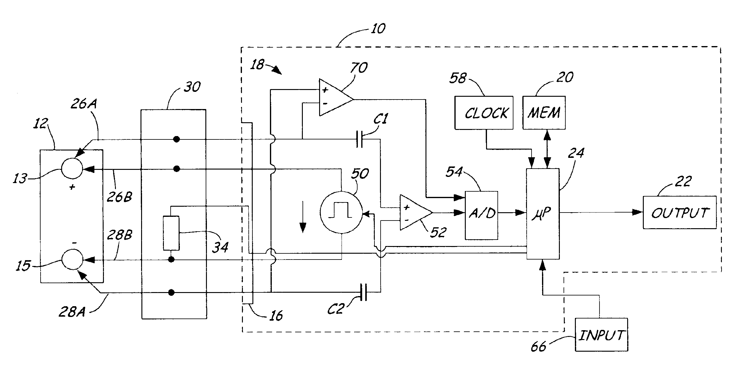
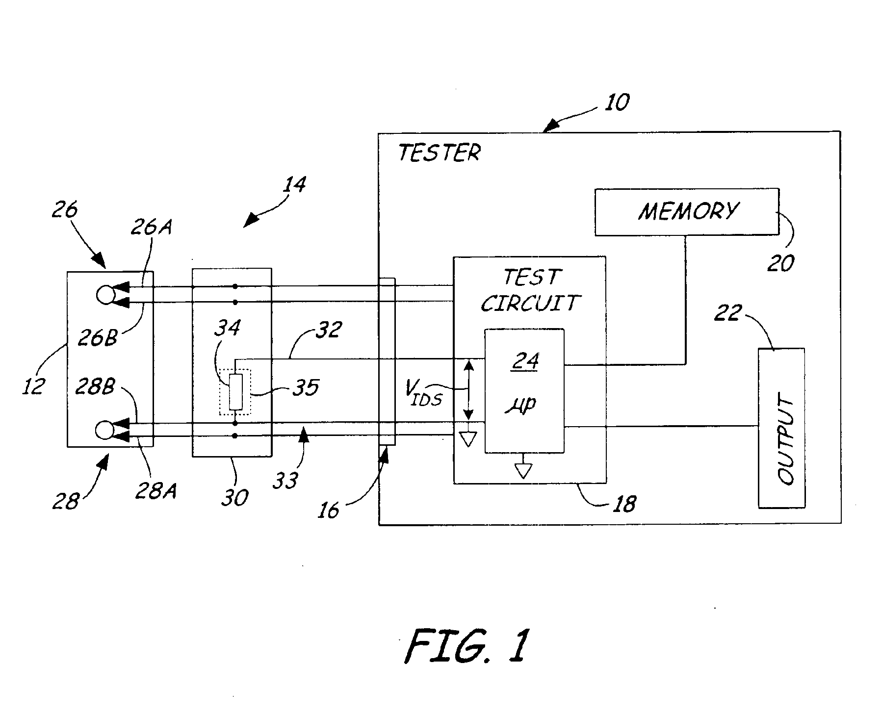
[0014]FIG. 1 is a very simplified block diagram of a battery tester 10 coupled to a battery 12 via a cable 14 in accordance with an illustrative embodiment of the present invention. The same reference numerals are used in the various figures to represent the same or similar elements. Note that FIG. 1 is a simplified block diagram of a specific type of battery tester. However, the present invention is applicable to any type of battery tester incl...


PUM


Abstract

An electronic battery tester connectable to a battery through any one of multiple cables. The tester includes an input that can couple to any one of the multiple cables. Also included is a memory that contains multiple calibration values, each calibration value corresponds to a different one of the multiple cables. Test circuitry, which is coupled to the input and to the memory, detects which one of the multiple cables is coupled to the input, and tests the battery as a function of one of the multiple calibration values that corresponds to the detected one of the multiple cables.

Description

BACKGROUND OF THE INVENTION[0001]The present invention relates to testing of storage batteries. More specifically, the present invention relates to an electronic battery tester capable of detecting the type of cable to which it is connected.[0002]Storage batteries, such as lead acid storage batteries of the type used in the automotive industry, have existed for many years. However, understanding the nature of such storage batteries, how such storage batteries operate and how to accurately test such batteries has been an ongoing endeavor and has proved quite difficult. Storage batteries consist of a plurality of individual storage cells electrically connected in series. Typically each cell has a voltage potential of about 2.1 volts. By connecting the cells in series, the voltages of the individual cells are added in a cumulative manner. For example, in a typical automotive storage battery, six storage cells are used to provide a total voltage when the battery is fully charged of 12.6...

Claims


Application Information

Patent Timeline
IPC IPC(8): G01R31/36
CPCG01R31/3648G01R31/3627G01R31/385
Inventor BERTNESS, KEVIN I.SMITH, CLARK E.KNOPF, ROGER S.
Owner MIDTRONICS
Why Eureka
Try Eureka