Image taking lens system

a lens system and image technology, applied in the field of image taking lens systems, can solve the problems of high-speed auto focusing difficulty, large amount of movement of the lens unit, and inability to achieve high-speed auto focusing, etc., to achieve the effect of quick effect focusing and correcting any fluctuations of aberrations resulting from focusing

Inactive Publication Date: 2005-05-10
CANON KK
View PDF7 Cites 16 Cited by
  • Summary
  • Abstract
  • Description
  • Claims
  • Application Information

AI Technical Summary

Benefits of technology

[0010]The present invention has as its object to provide an image taking lens system of a novel construction which can quickly effect focus...

Problems solved by technology

However, in the method whereby the first lens unit is moved in case of floating, the amount of movement of the lens unit generally becomes great.
Therefore, to adopt t...

Method used


Image

  • Image taking lens system
  • Image taking lens system
  • Image taking lens system

Examples


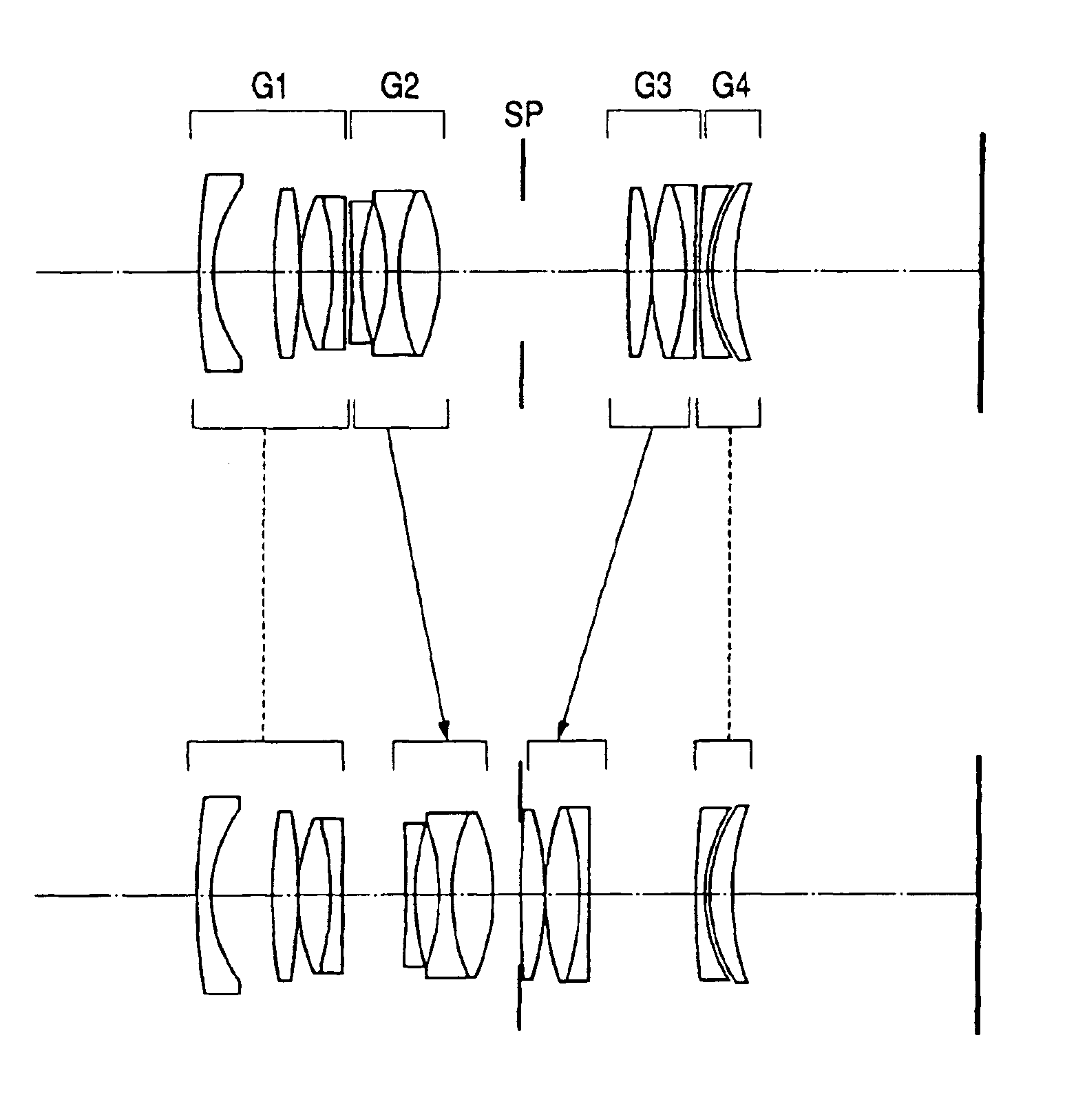
first numerical embodiment

[0047]

f = 50    Fno.2.8    2ω = 23°rdndνd1115.007721.996771.61271658.72221.784119.751385.7879441.80439839.594−72.702140.15224532.848084.918961.65159758.556−43.35621.849591.8466623.7871385.45509Variable8−166.084341.371371.88299740.76931.314313.742910−33.5462421.63999960.071131.035766.536941.83480742.7212−28.18164Variable13StopVariable14213.358153.167481.60311260.6415−47.371450.39551640.250735.59671.56383960.6717−37.05851.183091.8466623.7818−1788.00383Variable19221.142681.178441.77249949.602024.513160.637892124.589883.360481.76182126.522235.8033537.91209(Focusing on ∞)(Magnification: −0.5)(Magnification: −1.0)d71.3503164.7914710.1534d1213.01669.5794964.212328d1316.803528.3486890.4918d180.9171639.28432317.22968

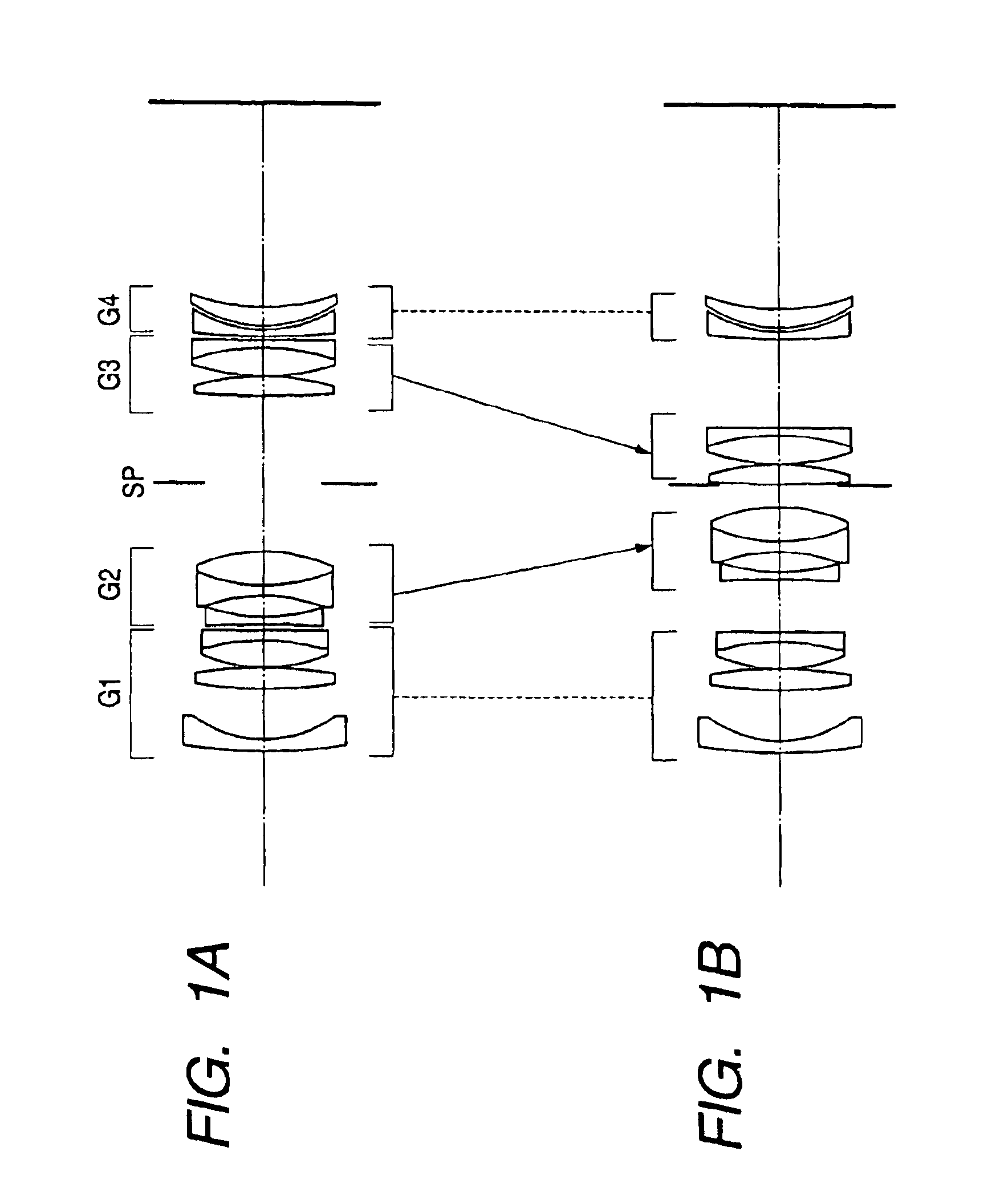
second numerical embodiment

[0048]

f = 50    Fno.2.8    2ω = 23°rdndνd166.5049821.80609840.92223.711839.83233394.5284541.80609840.924−59.835550.15525.987143.51.69679755.536−3741.269551.851.84666023.78764.68535Variable816401.704391.41.83480742.72924.149793.7246310−26.174391.41.60311260.641129.022646.51.78589644.2012−27.53037Variable13StopVariable14295.4312131.60311260.6415−44.275730.150031652.3867151.60311260.6417−40.745721.81.8466623.78181303.01099Variable1977.636081.51.71999550.222025.911812.124692127.3938931.71736229.502239.6010841.45224(Focusing on ∞)(Magnification: −0.5)(Magnification: −1.0)d71.934475.1778229.496911d128.893675.6501071.331522d1321.845539.0136350.461018d180.694609.2790222.07905

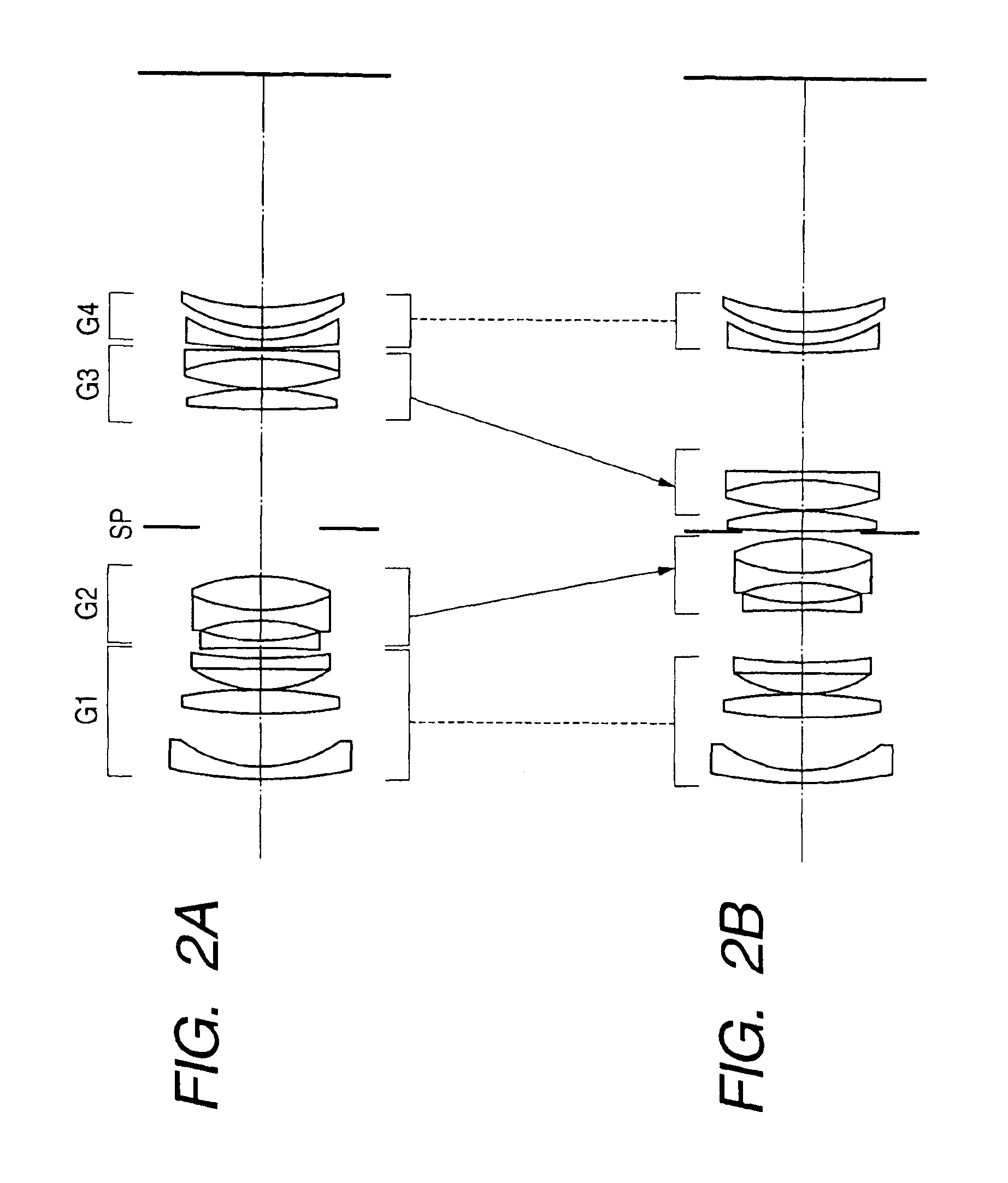
third numerical embodiment

[0049]

f = 50    Fno.2.8    2ω = 23°rdndνd1150.677351.836801.61271658.72222.573469.58301360.2700341.80439839.594−78.907920.14868535.749254.035651.65159758.556−48.292541.847641.8466623.787543.79648Variable8−878.882161.174371.88299740.76928.188803.5855410−29.8565621.63999960.071131.480636.327521.83480742.7212−29.80371Variable13StopVariable14216.274383.451841.60311260.6415−42.425900.074991643.418316.197881.56383960.6717−38.570821.121611.8466623.78181121.19301Variable19124.889781.139591.77249949.602024.609261.423522126.029163.597681.76182126.522240.2660142.70379(Focusing on ∞)(Magnification: −0.5)(Magnification: −1.0)d71.247054.8538589.898873d1213.062689.4560244.39846d1318.349519.3096860.439465d180.937109.51901917.4228


PUM


Abstract

This specification discloses an image taking lens system which can quickly effect focusing from an infinity object to a short-distance object. The image taking lens system disclosed in the present specification has, in succession from an object side to an image side, a first lens unit, a second lens unit, a third lens unit and a fourth lens unit. In case of focusing from the infinity object to the short-distance object, the first lens unit is not moved, but the second lens unit is moved to the image side and the third lens unit is moved to the object side. The principal point interval between the first lens unit and the second lens unit is a negative value.

Description

BACKGROUND OF THE INVENTION[0001]1. Field of the Invention[0002]This invention relates to an image taking lens system, and particularly to a so-called macrolens capable of photographing an infinity object to a short-distance object of a one-to-one magnification degree in a silver halide photographic camera, a video camera, a digital still camera or the like.[0003]2. Related Background Art[0004]As an image taking lens chiefly directed to the photographing of a short-distance object, there has heretofore been what is called a macrolens or a microlens (hereinafter referred to as the “macrolens”).[0005]The macrolens, as compared with other image taking lenses such as an ordinary standard lens and a telephoto lens, is designed such that high optical performance is obtained particularly in case of the photographing of a short-distance object.[0006]Also, in many cases, the macrolens is utilized for the photographing of objects at a wide range of distance including not only a short-distance...

Claims


Application Information

Patent Timeline
IPC IPC(8): G02B13/24G02B13/26G02B9/34G02B9/00G02B13/00
CPCG02B9/34G02B13/26G02B13/24
Inventor TAKI, YOSHIYUKI
Owner CANON KK
Why Eureka
Try Eureka