Eureka AIR delivers breakthrough ideas for toughest innovation challenges, trusted by R&D personnel around the world.

Apparatus and method for transmitting terrestrial signals on a common frequency with satellite transmissions

a satellite transmission and terrestrial signal technology, applied in the field of apparatus, can solve the problem that terrestrial and dbs signals on a common frequency cannot be utilized simultaneously

Inactive Publication Date: 2005-05-10
BROADBAND INVESTMENTS
View PDF12 Cites 8 Cited by
  • Summary
  • Abstract
  • Description
  • Claims
  • Application Information

AI Technical Summary

Benefits of technology

[0011]In order to ensure no interference between the satellite and terrestrially transmitted signals, the terrestrial signals are transmitted directionally within a terrestrial azimuth range which is outside the azimuth range in which the satellite signals are transmitted either by a single satellite or multiple satellites. The terrestrial transmission azimuth range is chosen so that it does no...

Problems solved by technology

Receiving signals in a range wider than the satellite spacing would cause interference by signals transmitted by different satellites on the same frequency.
However, since the signals received in the system shown in U.S. Pat. No. 5,483,663 are combined or received on the same antenna structure at different points in time, terrestrial and DBS signals on a common frequency cannot be utilized simultaneously.

Method used


Image

  • Apparatus and method for transmitting terrestrial signals on a common frequency with satellite transmissions
  • Apparatus and method for transmitting terrestrial signals on a common frequency with satellite transmissions
  • Apparatus and method for transmitting terrestrial signals on a common frequency with satellite transmissions

Examples


Embodiment Construction

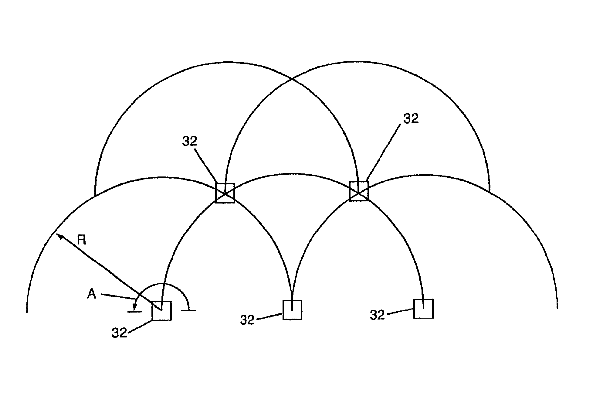
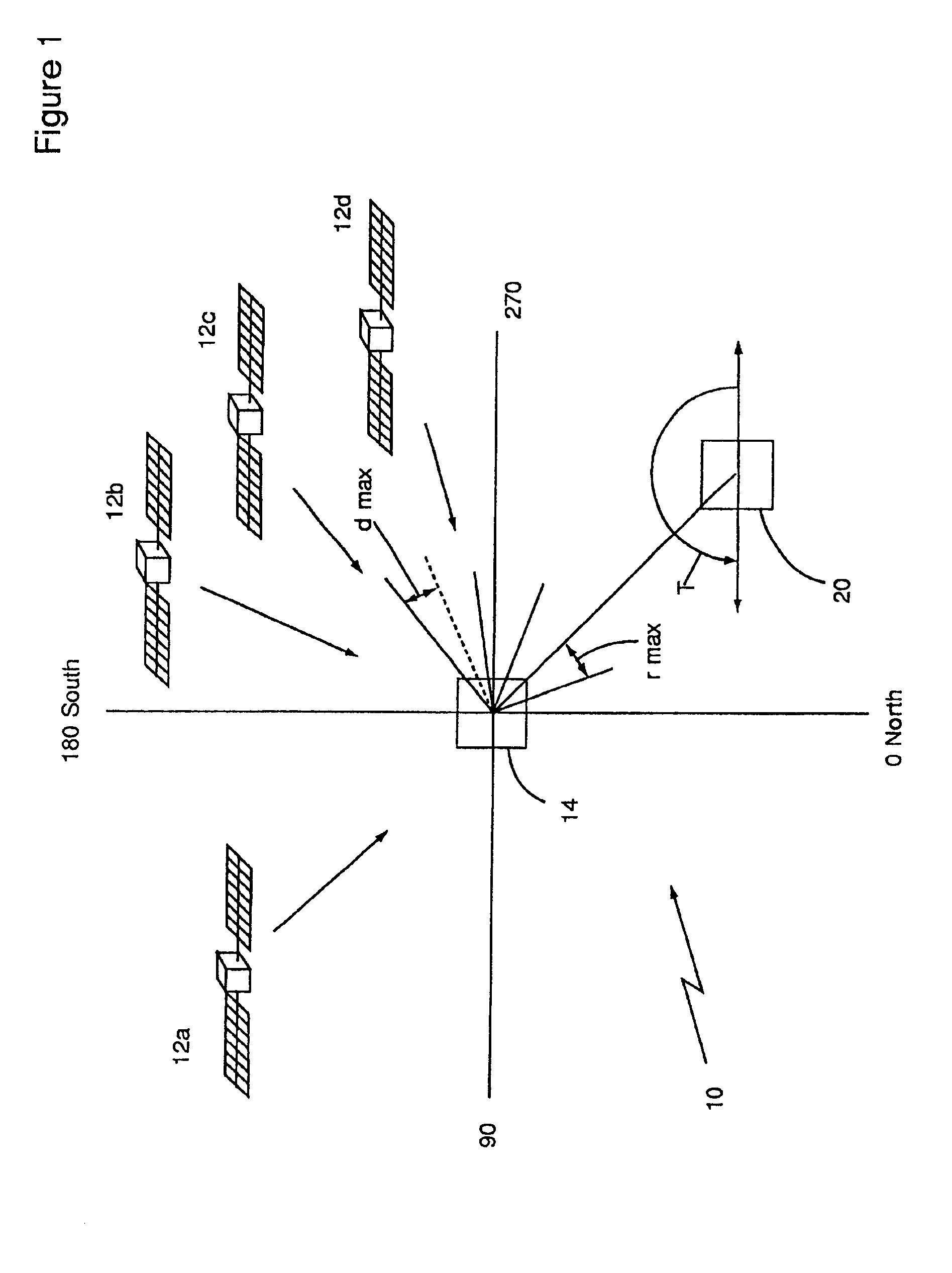
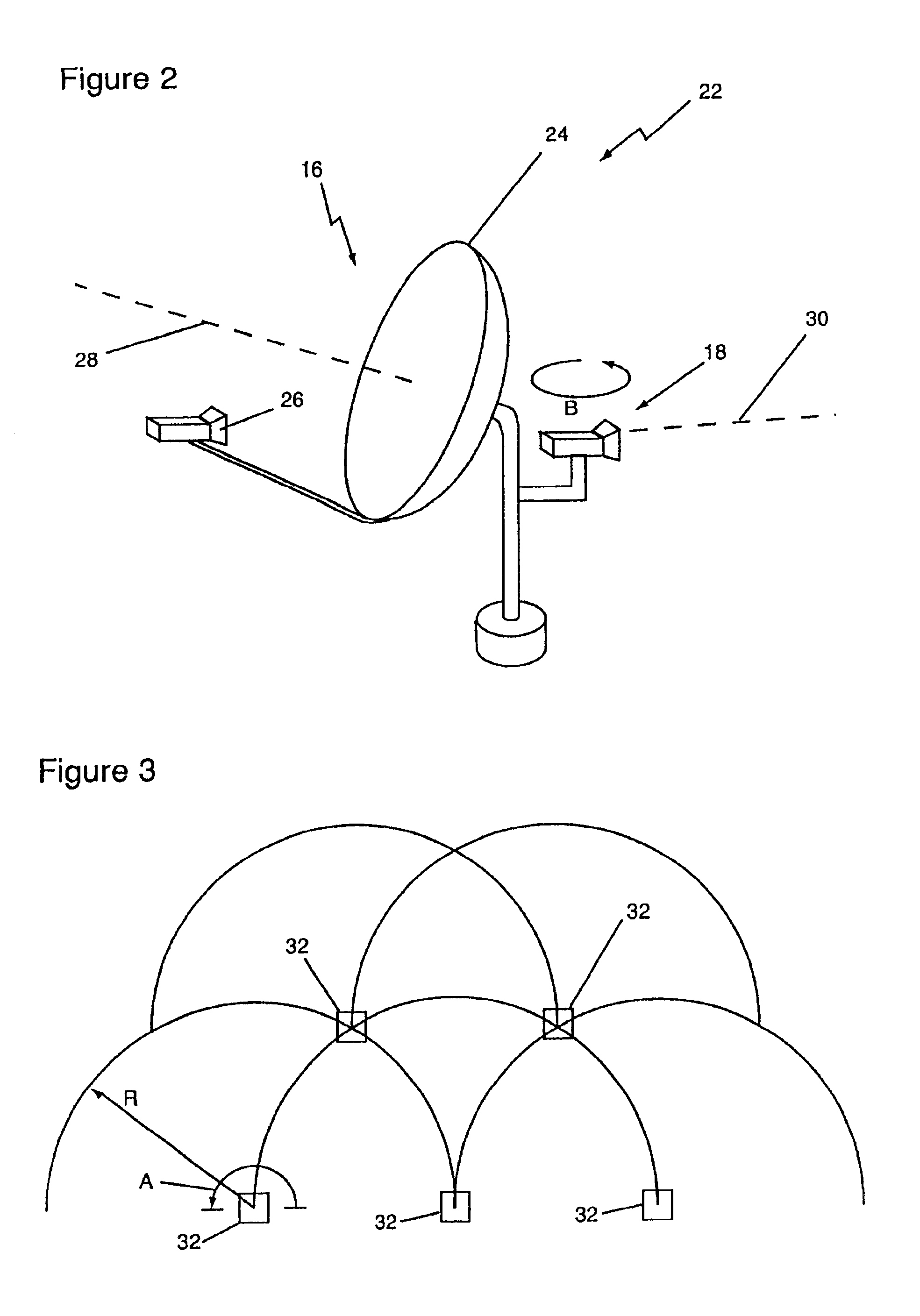
[0016]The apparatus according to the invention for providing terrestrially transmitted signals simultaneously on the same frequency as satellite signals is illustrated in FIGS. 1 and 2. As shown in FIG. 1, the system 10 may be utilized with one or more satellites in geosynchronous orbit about the earth. FIG. 1 shows four satellites 12a, 12b, 12c, and 12d spaced apart at four separate directions from a user location 14. In geosynchronous orbit, each satellite remains at a fixed location with respect to the earth's surface, and thus, with respect to the user location 14. First and second antenna 16 and 18, respectively, which will be discussed in detail with reference to FIG. 2 are located at the user location 14.

[0017]Each of these satellites 12a-d is positioned in geosynchronous orbit about the center of the earth, and is positioned at a certain longitude and latitude above the earth's surface. As is known by those skilled in the art, a receiving antenna may be directed at a certain...


PUM


Abstract

A first antenna (16) at a user location (14) receives signals at a first frequency where the signals are travelling only within a first directional reception range as measured from a centerline (28) of the first antenna (16). The first antenna (16) has its centerline (28) aligned to receive direct broadcast satellite signals transmitted from a satellite in geosynchronous orbit about the earth. A second antenna (18) at the user location (14) receives signals at the first frequency where the signals are travelling only within a second directional reception range as measured from a centerline (30) of the second antenna (18). The second antenna (18) is aligned to receive signals transmitted at the first frequency from a terrestrial transmitting location remote from the user location. A terrestrial transmitter transmits signals at the first frequency and directionally within a terrestrial azimuth range from the terrestrial transmitting location. The terrestrial transmitting location is located with respect to the user location (14) such that the terrestrial transmitter (20) transmits in directions only outside of the directional reception range of the first antenna (16). The satellite (12) is positioned with respect to the user location (14) such that the satellite transmits directional in directions outside of the directional reception range of the second antenna (18).

Description

[0001]This application is a continuation of application Ser. No. 08 / 991,265 filed Dec. 16, 1997, now U.S. Pat. No. 6,169,878, and which was a continuation of application Ser. No. 08 / 731,244, filed Oct. 11, 1996, now U.S. Pat. No. 5,761,605.BACKGROUND OF THE INVENTION[0002]This invention relates to devices and methods for broadcasting and receiving data, including digital television signals and voice signals. More particularly, this invention relates to an apparatus and method for providing terrestrial transmissions simultaneously along with direct broadcast satellite transmissions on a common frequency.[0003]Currently, television signals may be received from a satellite in geosynchronous orbit about the earth. The television signals are transmitted from a terrestrial transmitter to the satellite and then retransmitted from the satellite so that the signals can be received by terrestrial receivers within a certain geographic receiving area within a line of sight of the satellite. In ...

Claims


Application Information

Patent Timeline
IPC IPC(8): H04H1/00H04B7/185H04N7/20H01Q3/02H01Q25/02H04N5/38H04H40/90
CPCH04B7/18523H04N7/20H04H40/90
Inventor TAWIL, CARMENTAWIL, SALEEM
Owner BROADBAND INVESTMENTS
Why Eureka
Eureka Blog
Learn More