Movable display support system

Inactive Publication Date: 2005-05-17
STEELCASE INC
View PDF211 Cites 76 Cited by
  • Summary
  • Abstract
  • Description
  • Claims
  • Application Information

AI Technical Summary

Benefits of technology

[0008]It would be desirable to provide a system and method ha

Problems solved by technology

Where the display device is a conventional video monitor, it may be difficult (if not also inconvenient) to adapt the position of the display device to the needs of one or more workers who may have the need or desire to view or share information presented.
Likewise, it can be difficult to move the display device to a less prominent position within the work space, for example when information is to be viewed in private, or when the display device is not in use.
In any event, according to known arrangements, it is typically difficult as well as inconvenient to move a display device from an in-use position where information can be viewed and shared readily to a private or stowed position where information is not displayed or not to be shared by persons in the work space.
As a result, in many applications, display devices, once installed in a w

Method used


Image

  • Movable display support system
  • Movable display support system
  • Movable display support system

Examples


Embodiment Construction

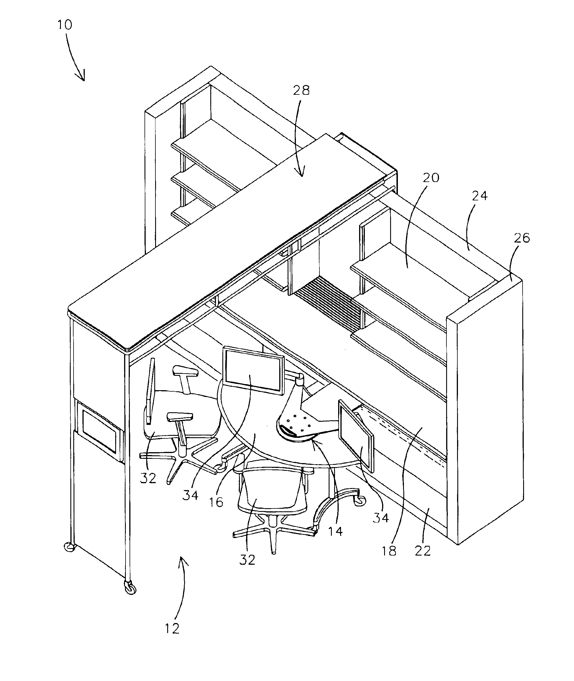
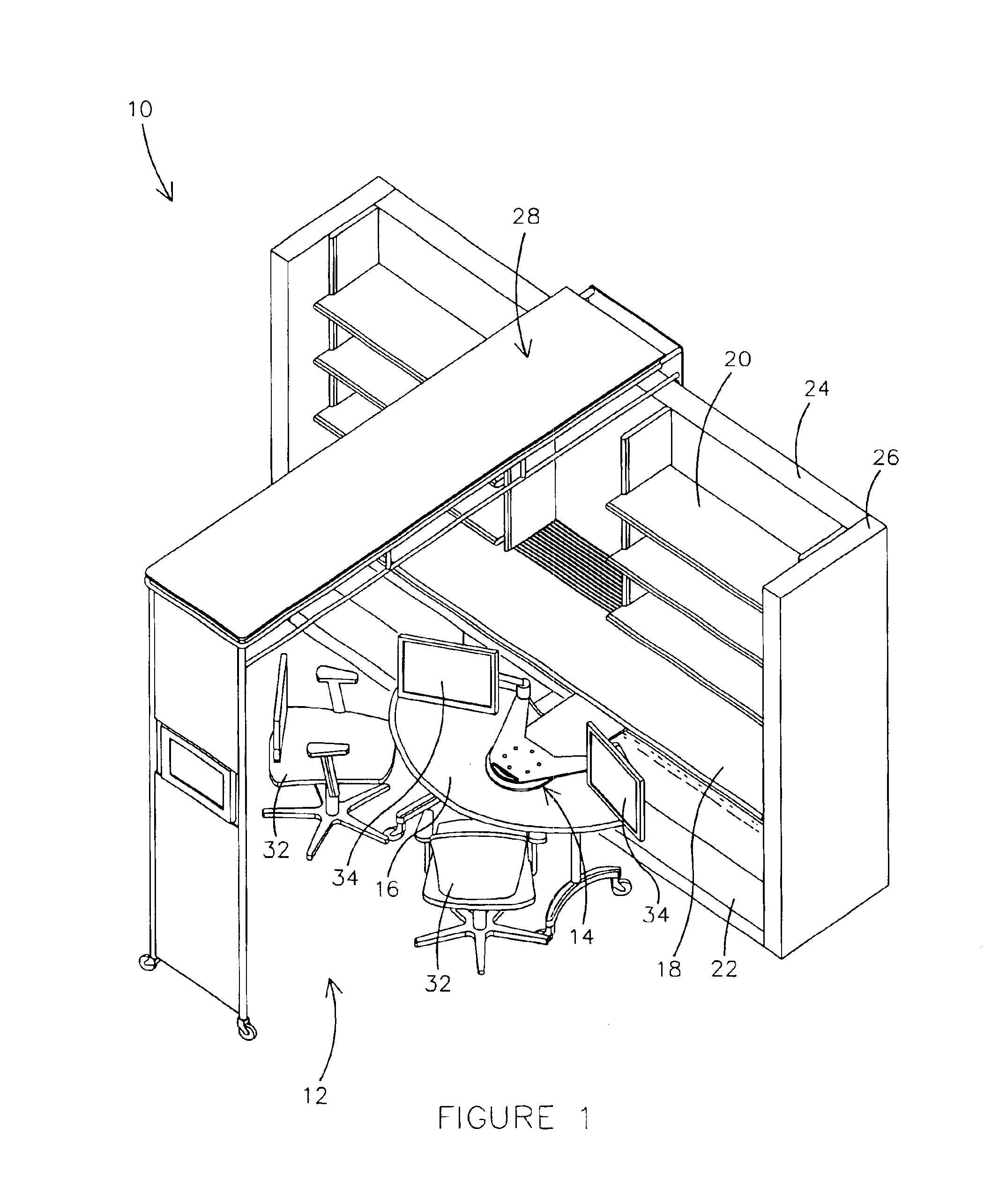
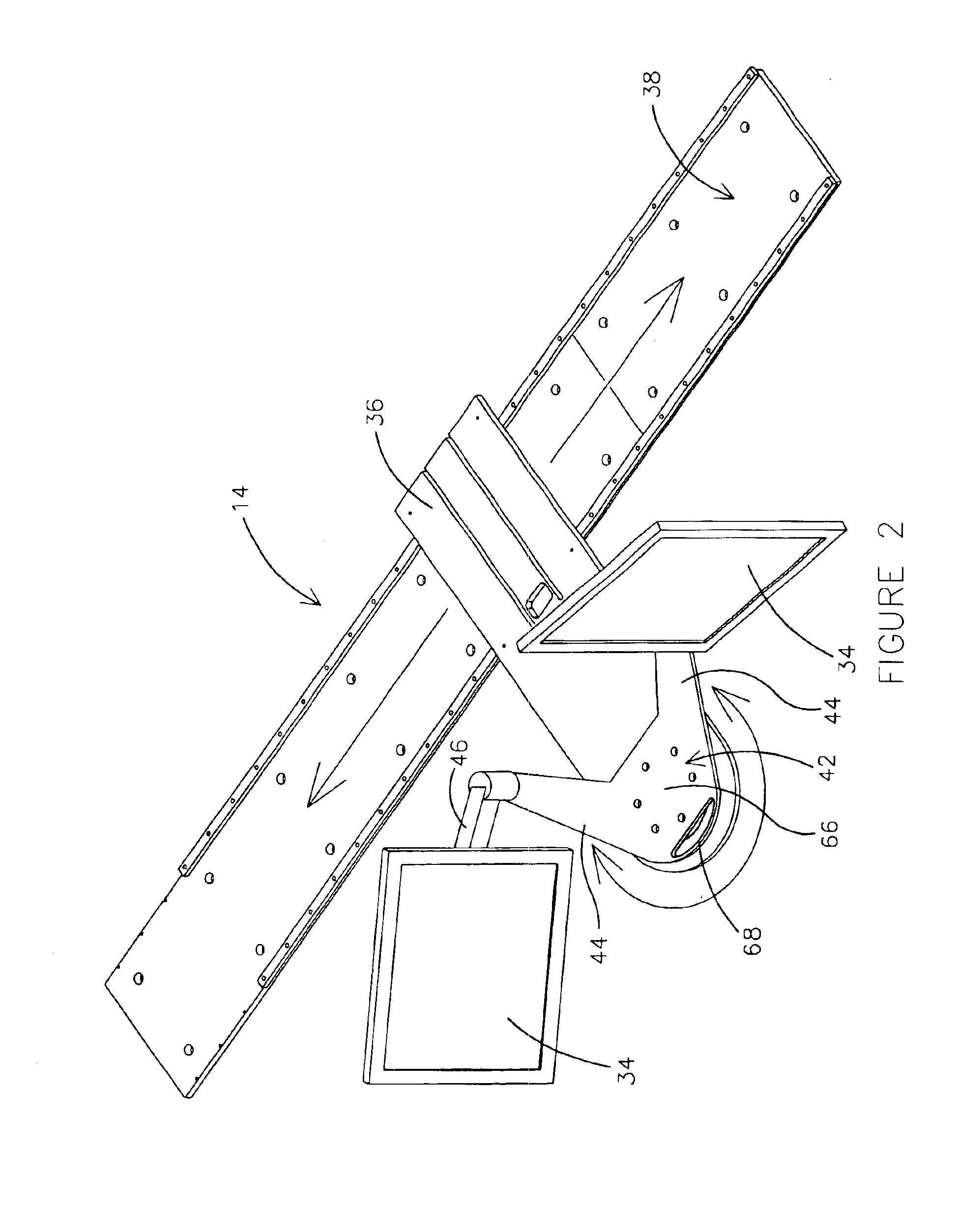
[0019]Referring to FIG. 1, a work space 10 is shown including a workstation 12 configurable for use by one or a plurality of workers or other persons. Workstation 12 includes a movable display support system 14 along with other articles of furniture shown as an associated mobile worksurface or table 16, a fixed worksurface 18, storage units shown as shelving units 20 and lateral files 22. Work space 10 also provides walls shown as partial height partition walls including a base wall 24 and side walls 26 as well as a utility threshold 28 movable on a track 30 (not visible in FIG. 1). According to any preferred embodiment, the utility threshold is of a type disclosed in U.S. patent application Ser. No. 09 / 183,023, titled “Workstation” and filed on Oct. 30, 1998, and in U.S. patent application Ser. No. 09 / 183,021, titled “Work Environment” and also filed on Oct. 30, 1998 (both incorporated by reference herein), providing functionality and features such as power, voice and data connecti...


PUM


Abstract

A movable support system for at least one display device is disclosed having a track system and a base movably mounted at a first section to the track system. A display support assembly adapted for coupling of the display device is pivotally mounted at a second section of the base. The display device installed on the display support assembly may be selectively positioned for use in a variety of locations relative to the track system. An apparatus is also disclosed providing a movable support for a display device, including a track system providing at least one track and a support movably coupled at a first section to the track system. The apparatus also includes a display support movably coupled to a second section of the support and configured for coupling at least two display panels. Each of the display panels may be positioned for use in a variety of locations relative to the track.

Description

CROSS-REFERENCE TO RELATED APPLICATIONS[0001]The following patents and / or patent applications are hereby incorporated by reference: U.S. patent application Ser. No. 09 / 888,069 titled “Movable Office Support System” filed Jun. 22, 2001 U.S. patent application Ser. No. 09 / 183,023 titled “Workstation” filed Oct. 30, 1998 now U.S. Pat. No. 6,374,547, now U.S. Pat. No. 6,375,547.FIELD OF THE INVENTION[0002]The present invention relates to a movable display support system. The present invention also relates to a support system for a display device or the like which is movable within a work space to support one or more workers in a wide variety of use conditions.BACKGROUND[0003]It is known to provide for a display device such as a display panel, video monitor (e.g. CRT), television screen or other video display to present information (in some form) for entertainment or use by one or more workers in an office or other work environment. Display devices are generally associated with electroni...

Claims


Application Information

Patent Timeline
IPC IPC(8): A47B21/03A47B21/00A47B83/00F16M11/04F16M11/00F16M11/42F16M11/02
CPCA47B21/00A47B21/03A47B21/0314A47B83/001A47B97/001F16M13/02F16M11/08F16M11/2014F16M11/2092F16M11/42F16M11/04
Inventor BALOGA, MARK A.FORSLUND, III, CARL V.FELDPAUSCH, THOMAS G.
Owner STEELCASE INC
Why Eureka
Try Eureka