Connector apparatus adapted for the direct plug-in connection of conductors

a technology of connecting apparatus and conductor, which is applied in the direction of electrical apparatus, coupling device connection, contact member penetrating/cutting insulation/cable strand, etc., can solve the problem that one must exert a relatively large force when connecting or disconnecting conductors, and achieves a high level of functional reliability, good elastic properties, and minimal cost

Active Publication Date: 2005-05-17
WEIDMULLER INTERFACE GMBH & CO KG
View PDF18 Cites 57 Cited by
  • Summary
  • Abstract
  • Description
  • Claims
  • Application Information

AI Technical Summary

Benefits of technology

[0011]The terminal, thus designed, can be switched from one side quite readily without any tools, whereas a conductor cannot again be taken out of it against the spring action without a tool. The terminal offers a high level of functional reliability with minimum costs and can be switched without any tools and can be disconnected with a tool.
[0012]It is conceivable that the bus bar display a recess that is bordered all around or that is open on one side and that helps when inserting a conductor end.
[0013]According to a further object of the invention, the connection device can also be arranged on a bus bar in various ways. This entails the need for using another part—the bus bar—but, on the other hand, it offers an advantage that must not be underestimated, in other words, the most suitable materials can be selected in each case for the spring and the contact of the bus bar. Whereas when one dispenses with the use of a bus bar, one must seek a material compromise; i.e., a material that has both good elastic properties and good contacting properties.

Problems solved by technology

While, on the one hand, this arrangement provides for an easy assembly of the components, it does present the problem that one must exert a relatively large force when connecting or disconnecting the conductors on other components of the connection device, for example, as a bus bar or a housing formed from an insulating material.

Method used


Image

  • Connector apparatus adapted for the direct plug-in connection of conductors
  • Connector apparatus adapted for the direct plug-in connection of conductors
  • Connector apparatus adapted for the direct plug-in connection of conductors

Examples


Embodiment Construction

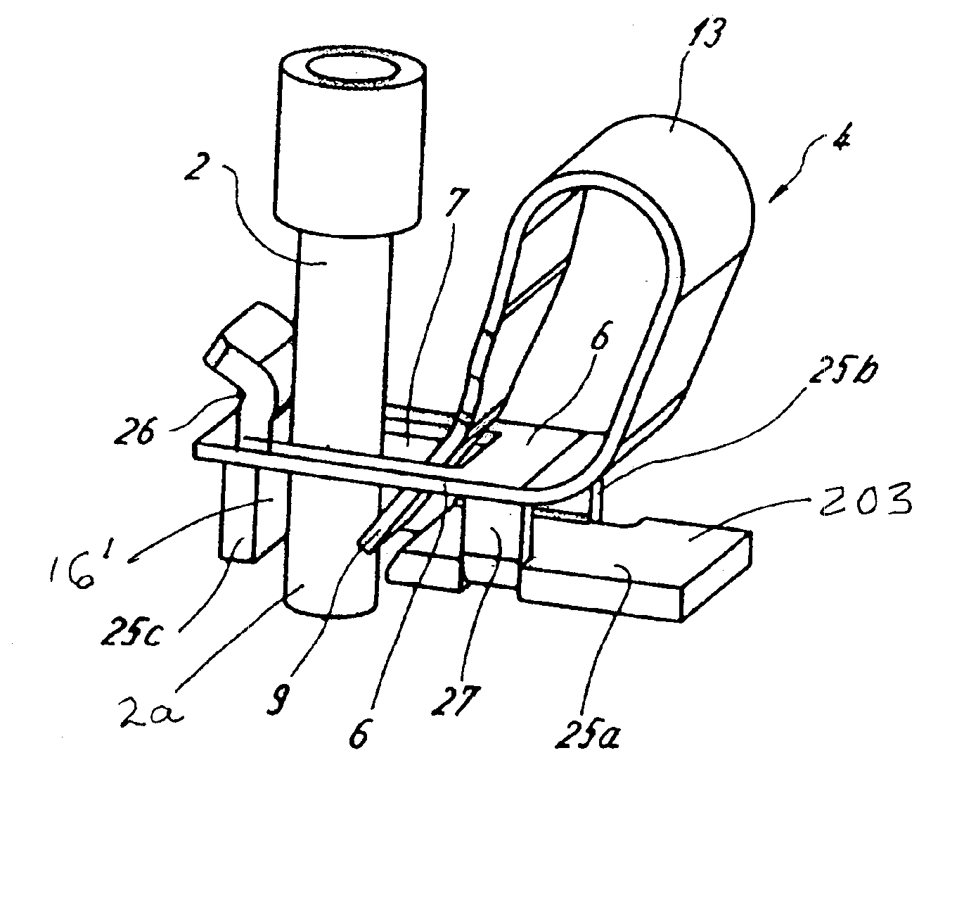
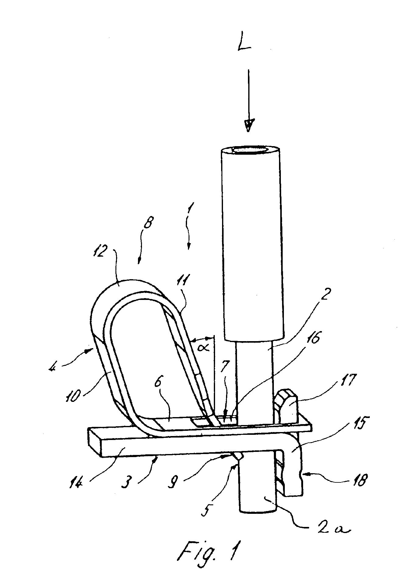
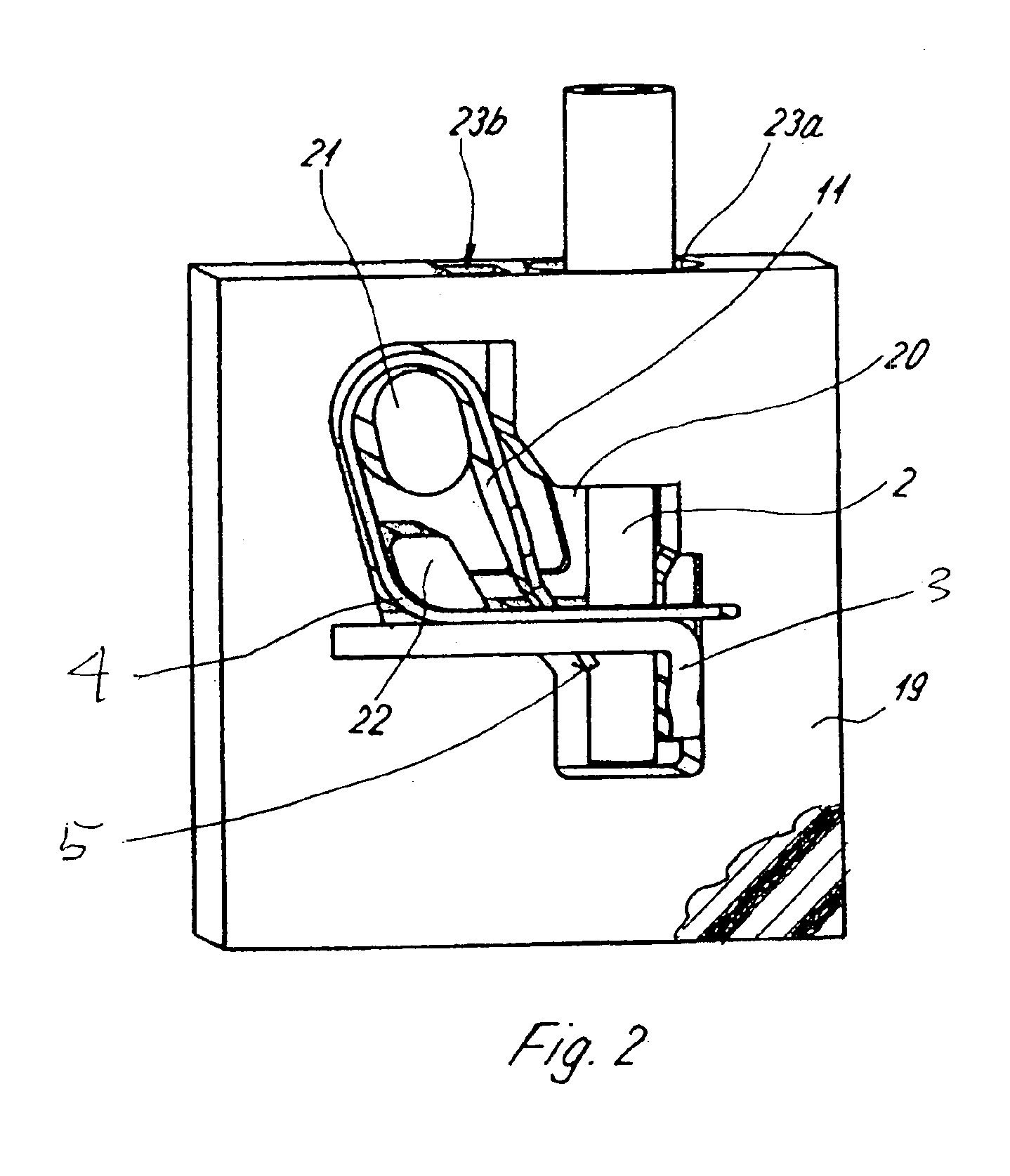
[0024]Referring first more particularly to FIG. 1, the connector arrangement 1 includes an insulated conductor 2 having a bare wire end portion 2a. A bus bar 3 is provided for supporting a resilient electrical contact 4 which serves as a pressure spring for firmly clamping conductor end 2a upon bus bar 3, the arrangement being so designed that conductor end 2 can be inserted directly into the clamping point 5 between resilient contact 4 and the bus bar without the use of any auxiliary insertion tool.

[0025]Resilient contact 4 has a first leg 6, which contains a window-like opening 7. Resilient contact 4 is mounted upon the bus bar with the first leg 6 above the window-like recess 7. Here, it is aligned parallel to the bus bar and it is placed upon it and / or attached upon it in a planar fashion. Alternatively, the first contact leg 6 can also be spaced at a distance away from the bus bar leg (as will be discussed below with reference to FIG. 4).

[0026]The resilient contact 4 includes a...


PUM


Abstract

An electrical connector arrangement includes a resilient contact adapted for direct engagement with the bare wire of an insulated conductor without the use of any assembly tool, characterized in that the resilient contact includes a first leg having a first end containing a window opening, a second leg having a first end extending at an acute angle through the window opening for clamping engagement with a conductor bare wire that is also inserted in the same direction therein, and a connecting portion connecting the other ends of the first and second legs to define a closed loop. A clamping edge at the extremity of the first end of the second resilient contact leg engages the bare wire and cooperates with a first edge of the window opening to prevent the withdrawal of the bare wire from the window opening. A conductive bus bar may be provided that includes a projecting portion that extends into the window opening between the bare wire and the window first edge, whereby the bare wire is clamped between the clamping edge of the second leg of the resilient contact and the bus bar projecting portion.

Description

BACKGROUND OF THE INVENTION[0001]1. Field of the Invention[0002]An electrical connector arrangement includes a resilient contact adapted for direct engagement with the bare wire of an insulated conductor without the use of any assembly tool, characterized in that the resilient contact includes a first leg having a first end containing a window opening, a second leg having a first end extending at an acute angle through the window opening for clamping engagement with a conductor bare wire that is also inserted in the same direction into the window opening, and a connecting portion connecting the other ends of the first and second legs to define a closed loop. A bus bar supports the resilient contact first leg and is provided with a projection that extends into the window opening between the conductor bare wire and the associated edge of the window opening.[0003]2. Description of the Related Art[0004]It is well known in the patented prior art to provide electrical connectors for conne...

Claims


Application Information

Patent Timeline
Patent Type & Authority Patents(United States)
IPC IPC(8): H01R31/08H01R4/48H01R31/00
CPCH01R31/08H01R4/4845H01R4/48455
Inventor DREWES, BJOERNBEINS, ECKARDFRICKE, HERBERTRICHTS, JOERGSTORM, SIEGFRIEDTAPPE, THOMASPRUESSNER, UDO
Owner WEIDMULLER INTERFACE GMBH & CO KG
Why Eureka
Try Eureka