Remote control apparatus with user-operated clutch controls

a remote control and clutch technology, applied in the field of remote control devices, can solve the problems of not including an independent control for braking the remote control vehicle, no control is provided on the hand-held controller for operating the clutch for changing gears, and the patent does not disclose the hand-held controller which includes the clutch

Inactive Publication Date: 2005-05-17
CAIOZZA JOSEPH C
View PDF5 Cites 33 Cited by
  • Summary
  • Abstract
  • Description
  • Claims
  • Application Information

AI Technical Summary

Benefits of technology

[0014]To achieve the foregoing and other advantages, the present invention, briefly described, provides a remote control apparatus which includes a transmission controller unit and a transmitter unit electrically connected to the transmission controller unit. The transmission controller unit includes a transmission-controller-unit housing. A transmission-controller-unit handle is formed from a portion of the transmission-controller-unit housing. An accelerator control finger lever projects outward from a first side portion of the transmission-controller-unit housing. A brake control finger lever projects outward from the first side portion of the transmission-controller-unit housing. A clutch thumb lever projects outward f...

Problems solved by technology

Moreover, this device does not include an independent control for braking the remote controlled vehicle.
Moreover, no control is provided on the hand-held controller for operating a clutch for changing gears.
As with other patents discussed above, this patent does not disclose a hand-held controller which includes a clutch control.
In general, prior art remote controlled vehicles are not controlled by separate clut...

Method used


Image

  • Remote control apparatus with user-operated clutch controls
  • Remote control apparatus with user-operated clutch controls
  • Remote control apparatus with user-operated clutch controls

Examples


Embodiment Construction

[0062]With reference to the drawings, a new and improved remote control apparatus embodying the principles and concepts of the present invention will be described.

[0063]In all FIGS. 1-12, reference numerals are shown that correspond to like reference numerals that designate like elements shown in the other figures.

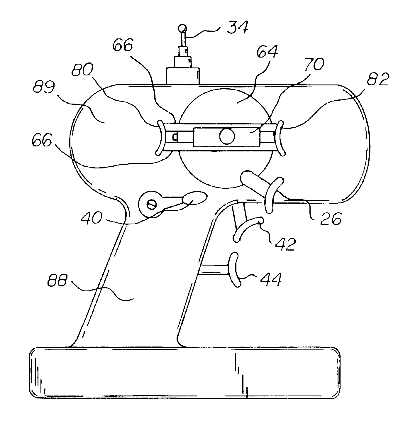
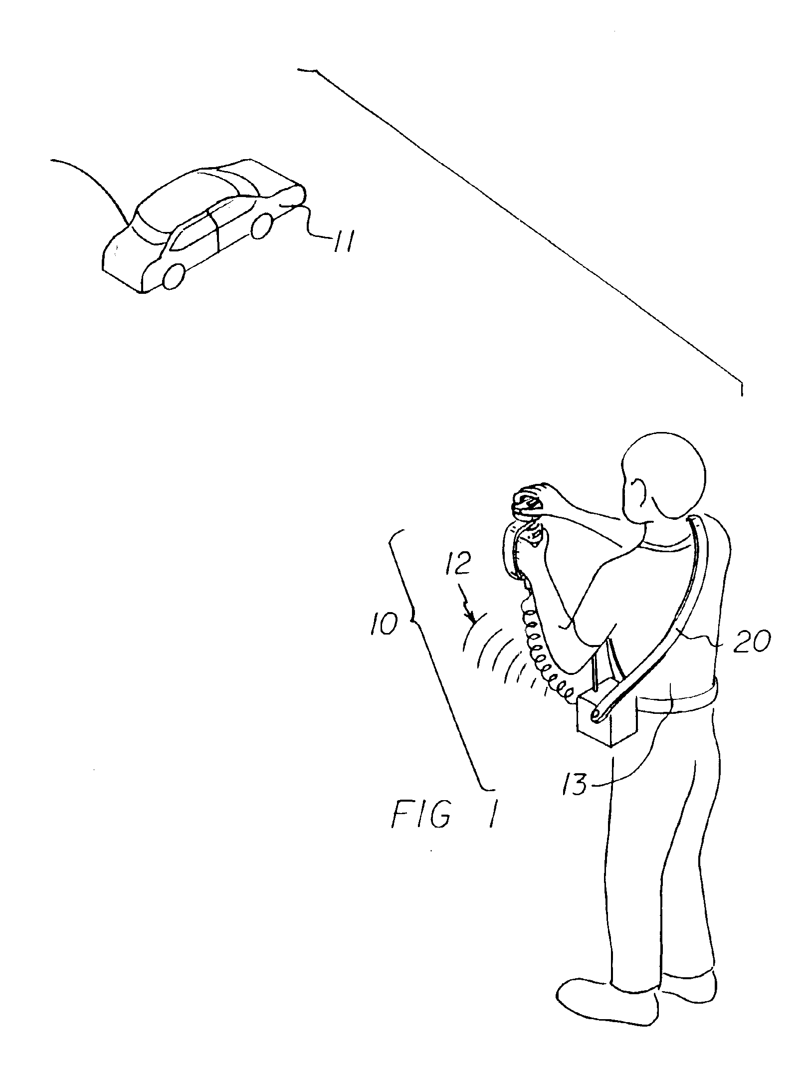
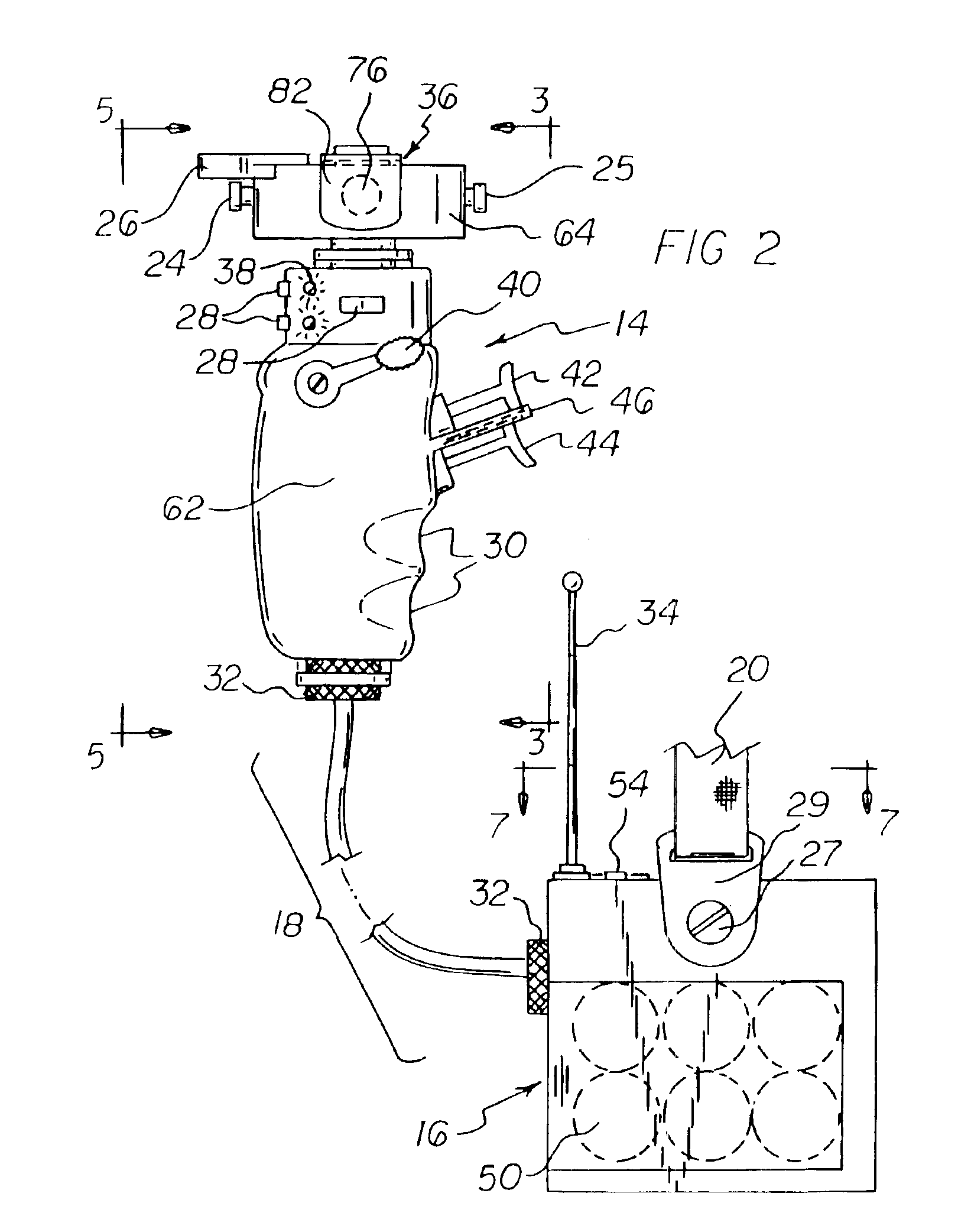
[0064]Turning to FIGS. 1-7, there is shown a first embodiment of the remote control apparatus of the invention generally designated by reference numeral 10. With the first embodiment, a remote control apparatus 10 includes a transmission controller unit 14 and a transmitter unit 16 electrically connected to the transmission controller unit 14. The transmission controller unit 14 includes a transmission-controller-unit housing. A transmission-controller-unit handle 62 is formed from a portion of the transmission-controller-unit housing. An accelerator control finger lever 42 projects outward from a first side portion of the transmission-controller-unit housing. A brake cont...


PUM


Abstract

An ergonomically comfortable remote control apparatus includes a transmission controller unit and a transmitter unit electrically connected together. The transmission controller unit includes a transmission-controller-unit handle. An accelerator control finger lever and a brake control finger lever project outward from a first side of the transmission-controller-unit handle. A clutch thumb lever projects outward from a second side of the transmission-controller-unit handle. A steering wheel is connected to a portion of the transmission-controller-unit handle at a location above the accelerator control finger lever, the brake control finger lever, and the clutch thumb lever. A finger-operated steering control handle is connected to the steering wheel. A hand operated gear shift slide actuator is supported on the steering wheel and operates an upshift actuator button and a downshift actuator button located on the steering wheel.

Description

BACKGROUND OF THE INVENTION[0001]1. Field of the Invention[0002]The present invention relates generally to remote control devices, and, more particularly, to radio-controlled remote control devices which are controlled by a hand-held controller.[0003]2. Description of the Prior Art[0004]Radio-controlled remote control devices which are controlled by a hand-held controller are well known in the art. In this respect, throughout the years, a number of innovations have been developed relating to such radio-controlled remote control devices, and the following U.S. Pat. Nos. are representative of some of those innovations: 4,865,575, 5,024,626, 5,195,920, 5,334,075, and 5,785,576.[0005]More specifically, U.S. Pat. No. 4,865,575 discloses a light-responsive remote control vehicle that runs along a track that includes vertical side walls. In this respect, the vehicle does not include means for steering the vehicle. Also, in this respect, the hand-held controller does not include means for c...

Claims


Application Information

Patent Timeline
IPC IPC(8): A63H30/00A63H30/04
CPCA63H30/04
Inventor CAIOZZA, JOSEPH C.
Owner CAIOZZA JOSEPH C
Why Eureka
Try Eureka