Apparatus and method for fluid injection

a fluid injection and apparatus technology, applied in the field of fluid processing, can solve the problems of large improvement room, lack of flexibility of current microfluidic devices, and devices using micro-scale implementations of traditional approaches

Inactive Publication Date: 2005-05-17
BOARD OF RGT THE UNIV OF TEXAS SYST
View PDF49 Cites 45 Cited by
  • Summary
  • Abstract
  • Description
  • Claims
  • Application Information

AI Technical Summary

Benefits of technology

[0025]In another respect, the invention relates to a method for metered injection of a fluid packet. A vessel containing a first fluid is pressurized to a pressure less than or equal to a hold off pressure, the first fluid including a first dielectric material, One or more electrodes coupled to a surface adjacent the vessel are energized, the surface including a second fluid comprising a second dielectric material. The first fluid is subjected to an extraction force from the one or more electrodes to form the fluid packet and extract the fluid packet from the vessel onto a surface.
[0026]In another respect, the invention relates to an apparatus for injecting a fluid packet onto a surface. The apparatus includes a vessel, a pressure manifold, a pressure reservoir, and a device capable of generating a programmable extraction force. The vessel is configured to contain a fluid. The pressure manifold is coupled to the vessel. The pressure reservoir is coupled to the manifold and is configured to pressurize the vessel to a pressure less than or equal to a hold off pressure. The extraction force is configured to form the fluid packet and extract the fluid packet from the vessel onto the surface. There may be two or more pressure reservoirs or the vessel may comprise a flow-through injector.
[0027]In yet another respect, the invention relates to an apparatus for moving a fluid packets. The apparatus includes a vessel, a pressure manifold, a pressure reservoir, a device capable of generating a programmable extraction force and an exit port. The vessel is configured to contain a fluid. The pressure manifold is coupled to the vessel. The pressure reservoir is coupled to the manifold and is configured to pressurize the vessel to a pressure less than or equal to a hold off pressure. The extraction force is configured to form the fluid packet and extract the fluid packet from the vessel onto the surface. The exit port is coupled to the surface and configured to receive the fluid packet. The exit port is preferably hydrophilic. There can be a plurality of exit ports. A conventional fluidics device may be coupled to the exit port.
[0028]The vessel may comprise a flow-through injector, and th...

Problems solved by technology

While devices using micro-scale implementations of these traditional approaches may exhibit at least a degree of utility, vast room for improvement remains.
For instance, current microfluidic devices lack flexibility for they rely upon a fixed pathway of microchannels.
With fixed pathways, devices are limited in the number and type of tasks they may perform.
Also, using fixed pathways makes many types of metering, transport, and manipulation difficult.
With traditional devices, it is difficult to partition one type of sample from another within a channel.
Although useful for determining particle dielectrophoretic properties, such a system is limited in application.
In particular, such a system does not allow for general fluidic processing involving various interactions, sometimes performed simultaneously, such as metering, mixing, fusing, transporting, division, and general manipulation of multiple reagents and reaction products.
In particular, such a system, utilizing attachment sites for certain binding entities is designed for particular applications and not for general fluidic processing of a variety of fluids.
Although useful for tasks such as separation, room for improvement remains in that such devices are not well suited for performing a wide variety of fluidic processing interactions on a wide variety of different materials.
While perhaps useful for facilitating certain interactions b...

Method used


Image

  • Apparatus and method for fluid injection
  • Apparatus and method for fluid injection
  • Apparatus and method for fluid injection

Examples


example 1

Programmable Fluid Processor

[0071]In one embodiment, packets of metered size may be injected from one or more inlet ports on the sidewall(s) of a programmable fluid processor (PFP), such as the apparatus described in U.S. patent application Ser. No. 09 / 249,955, now U.S. Pat. No. 6,294,063 by dielectrophoresis into an immiscible carrier liquid covering a reaction surface.

[0072]Fluid flow may be made to be digital, rather than continuous, in the PFP, and the packets may be controlled electronically. The only moving parts in such a setup will be the fluid packets, and no valves or mechanical pumps will be required. Injectors according to the present disclosure may be attached directly to adjacent reservoirs containing reagents or any other suitable fluid or gas. Packets may vary widely in size, but in one embodiment may have diameters from about 20 to about 100 μm. The packets may have volumes that vary widely, but in one embodiment the volumes may be in the 0.1 to 1 nL range. On-chip ...

example 2

Fluid Processing System

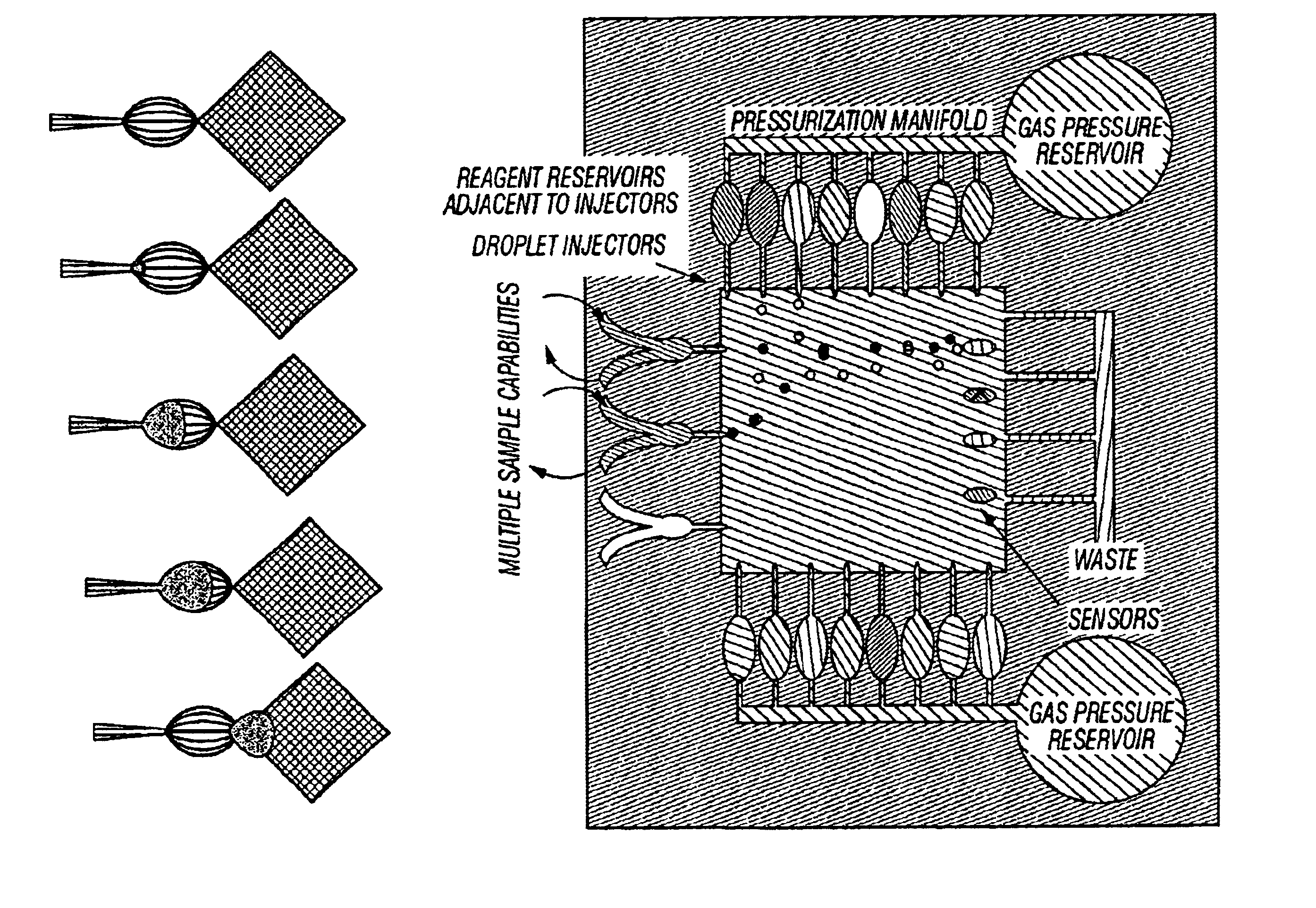
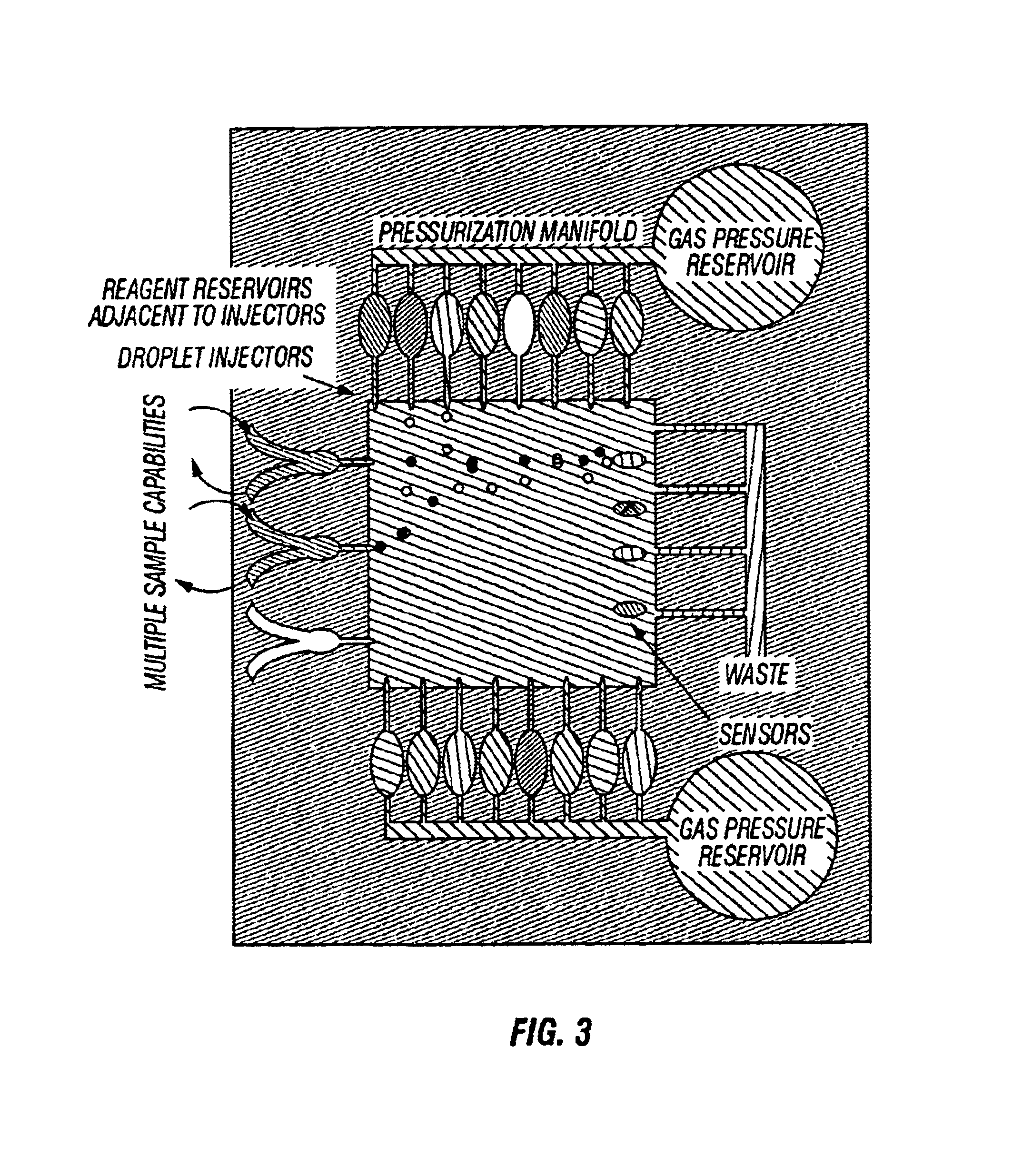
[0076]FIG. 4 shows a block diagram of a fluid processing system that uses injection technology in accordance to the embodiments disclosed herein. On the right side of FIG. 4 is shown a fluidic processing apparatus termed the “BioFlip.” This may vary in size significantly, but in one embodiment its size may be about 3″×2″×0.5″. It may be in the form of a cartridge equipped with no more user interface than an alarm and a small LCD. It may be self-contained and operate autonomously. It may be programmable by a handheld unit (Windows CE or Gameboy-style) shown on its left.

[0077]The packet injection of material from the sample and reagent reservoirs may be controlled by dielectrophoresis with a no moving parts, the packet size may be controlled by varying parameters discussed above and listed in Table 1 such as orifice size and / or pressure, the packets may be moved anywhere on a two-dimensional array via dielectrophoresis or another suitable manipulation force, the...

example 3

Pressure Relationships

[0080]The static pressure differential necessary to maintain a packet is generally expressed by: Pi⁢ ⁢n-Pext=γr

where Pin and Pext are the internal and external hydrostatic pressures, γ is the surface tension and r is the radius of the packet. Thus, the pressure differential necessary to maintain a packet is inversely proportional to the radius of the packet.

[0081]Since water adheres to hydrophilic glass, injected packets tend to remain attached to the tip of the injector pipettes unless the outer surface is made hydrophobic. This may be done by dip-coating the pipettes in a anti-wetting agent such as, but not limited to, Sigmacote®, a silicone solution in heptane, or a fluoropolymer, such as PFC1601A from Cytonix, Inc.

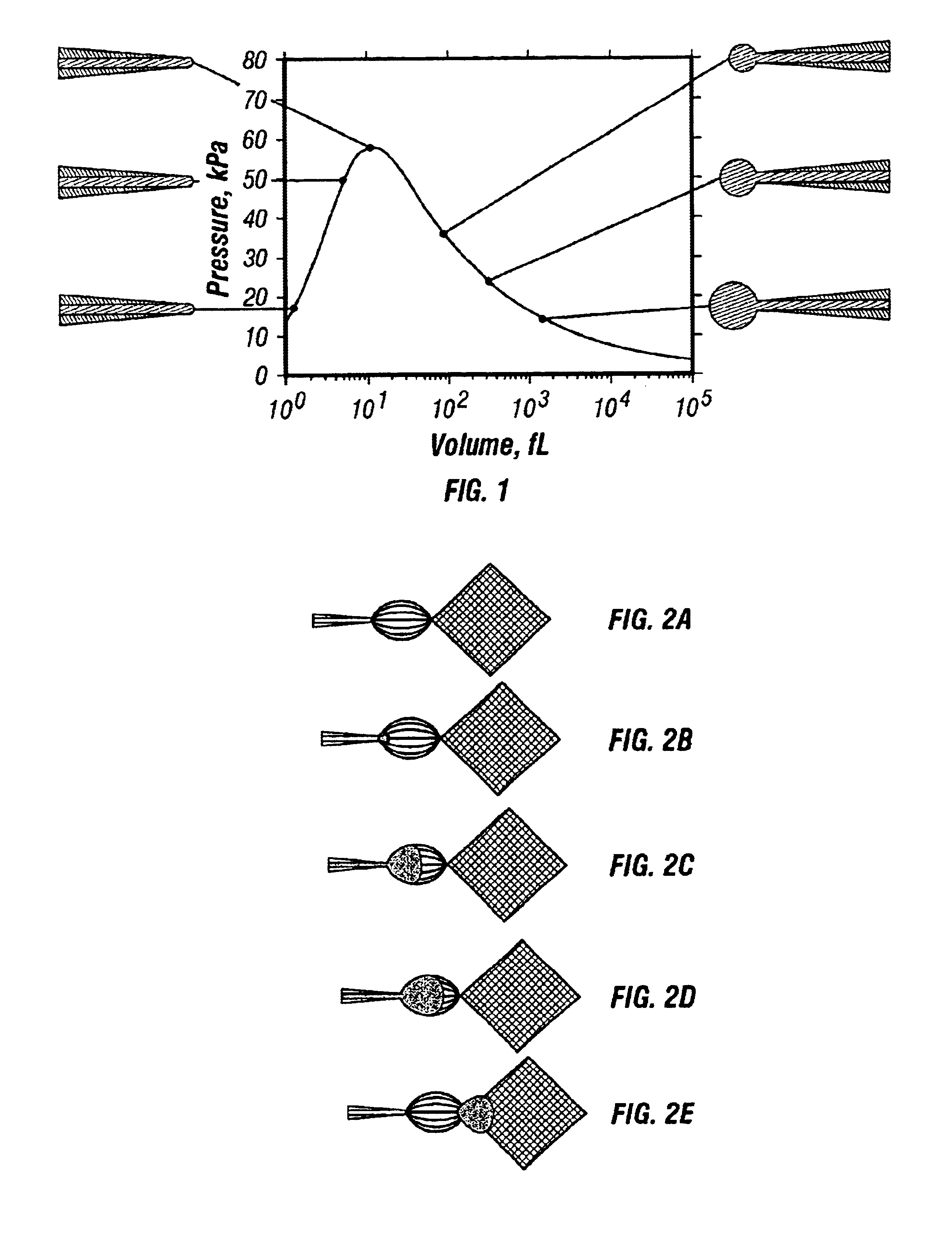
[0082]The pressure inside a packet is inversely proportional to its radius. Therefore, if the meniscus is flat at the injector tip, it has infinite radius and zero pressure. As fluid flows to form a nascent packet, the meniscus radius decreases un...


PUM

PropertyMeasurementUnit
Fractionaaaaaaaaaa
Fractionaaaaaaaaaa
Fractionaaaaaaaaaa

Abstract

Methods and apparatuses for metered injection of a fluid packet. A vessel containing a fluid is pressurized to a pressure less than or equal to a hold-off pressure. The fluid is subjected to an extraction force to form the fluid packet and extract the fluid packet from the vessel onto a surface.

Description

[0001]The present invention claims priority to U.S. Provisional Application No. 60 / 211,516 filed Jun. 14, 2000, herein incorporated by reference.[0002]The government may own rights in the present invention pursuant to grant number N66001-97-C-8608 modification 3 from the Defense Advanced Research Projects Agency.BACKGROUND OF THE INVENTION[0003]1. Field of the Invention[0004]The present invention relates generally to fluidic processing and, more particularly, to methods and apparatuses to controllably inject fluid packets onto a surface. Even more particularly, the present invention relates to methods and apparatuses for programmably injecting fluid packets onto a surface using dielectrophoretic forces.[0005]2. Description of Related Art[0006]Chemical protocols often involve a number of processing steps including metering, mixing, transporting, division, and other manipulation of fluids. For example, fluids are often prepared in test tubes, metered out using pipettes, transported in...

Claims


Application Information

Patent Timeline
IPC IPC(8): B01L3/00B03C5/00B01J4/02
CPCB01L3/5027B01L3/502715B01L3/50273B01L3/502784B01L3/502792B03C5/005B01L2200/0605B01L2300/0816B01L2300/0877B01L2300/089B01L2400/0415B01L2400/0424B01L2400/0487B01L2200/0673
Inventor GASCOYNE, PETERVYKOUKAL, JODY V.SCHWARTZ, JONBECKER, FREDERICK F.
Owner BOARD OF RGT THE UNIV OF TEXAS SYST
Why Eureka
Try Eureka