
Radiation detector having a unitary reflector part composed of plastic containing an optically reflective filler

a technology of optical reflection and radiation detector, which is applied in the field of radiation detector, can solve the problems of complicated and difficult positioning of scattered radiation collimators, more difficult, if not impossible, to effect the exact positioning of scintillators relative to photodiodes, etc., and achieves the effect of simple and uncomplicated manner

Inactive Publication Date: 2005-05-17
SIEMENS HEALTHCARE GMBH
View PDF13 Cites 11 Cited by
  • Summary
  • Abstract
  • Description
  • Claims
  • Application Information

AI Technical Summary

Benefits of technology

[0014]An object of the present invention is to provide a radiation detector of the type mentioned in the introduction which can be produced in a simple and uncomplicated manner.

Problems solved by technology

In this case, the scintillators are not separate elements since this would make it more difficult, if not impossible, to effect the exact positioning of the scintillators relative to the photodiodes.
If it is intended to use a scattered radiation collimator, in both manufacturing concepts it is complicated and difficult to position the scattered radiation collimator before the adhesive bonding to the radiation detector or detector modules relative to the latter in the required manner.
Therefore, complicated apparatuses are used in which the scattered radiation collimator and the radiation detector or the detector module must remain until the adhesive bonding has cured.

Method used


Image

  • Radiation detector having a unitary reflector part composed of plastic containing an optically reflective filler
  • Radiation detector having a unitary reflector part composed of plastic containing an optically reflective filler
  • Radiation detector having a unitary reflector part composed of plastic containing an optically reflective filler

Examples


Embodiment Construction

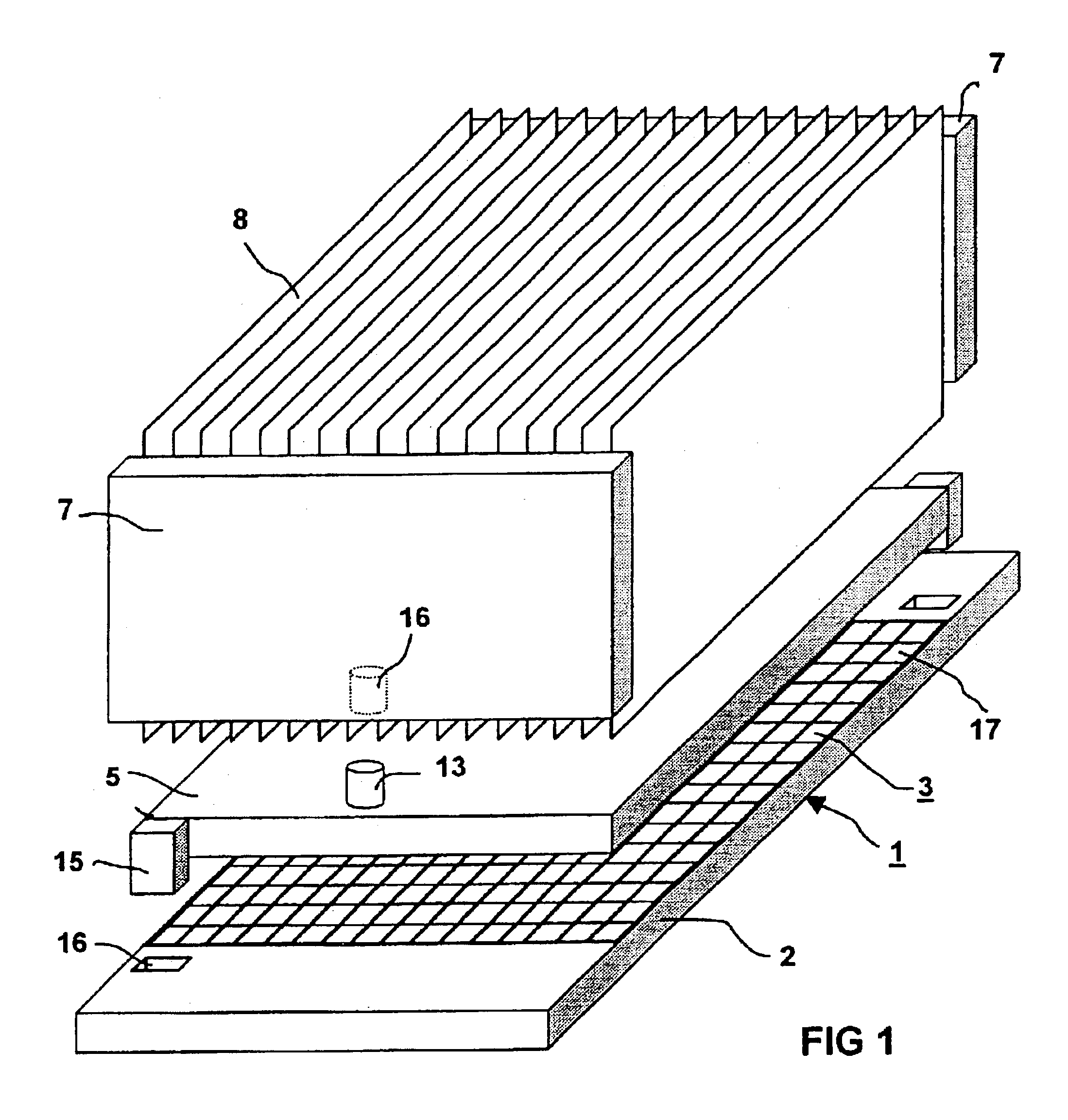
[0029]As can be seen in FIG. 1, the exemplary embodiment of a radiation detector according to the invention which is illustrated in FIGS. 1 to 3 has, as essential elements, a photodiode arrangement 1 with photodiodes 3 fitted on a substrate 2, a reflector part 5 containing scintillators 4 and a scattered radiation collimator 6 with collimator plates 8 fitted between two side parts 7.

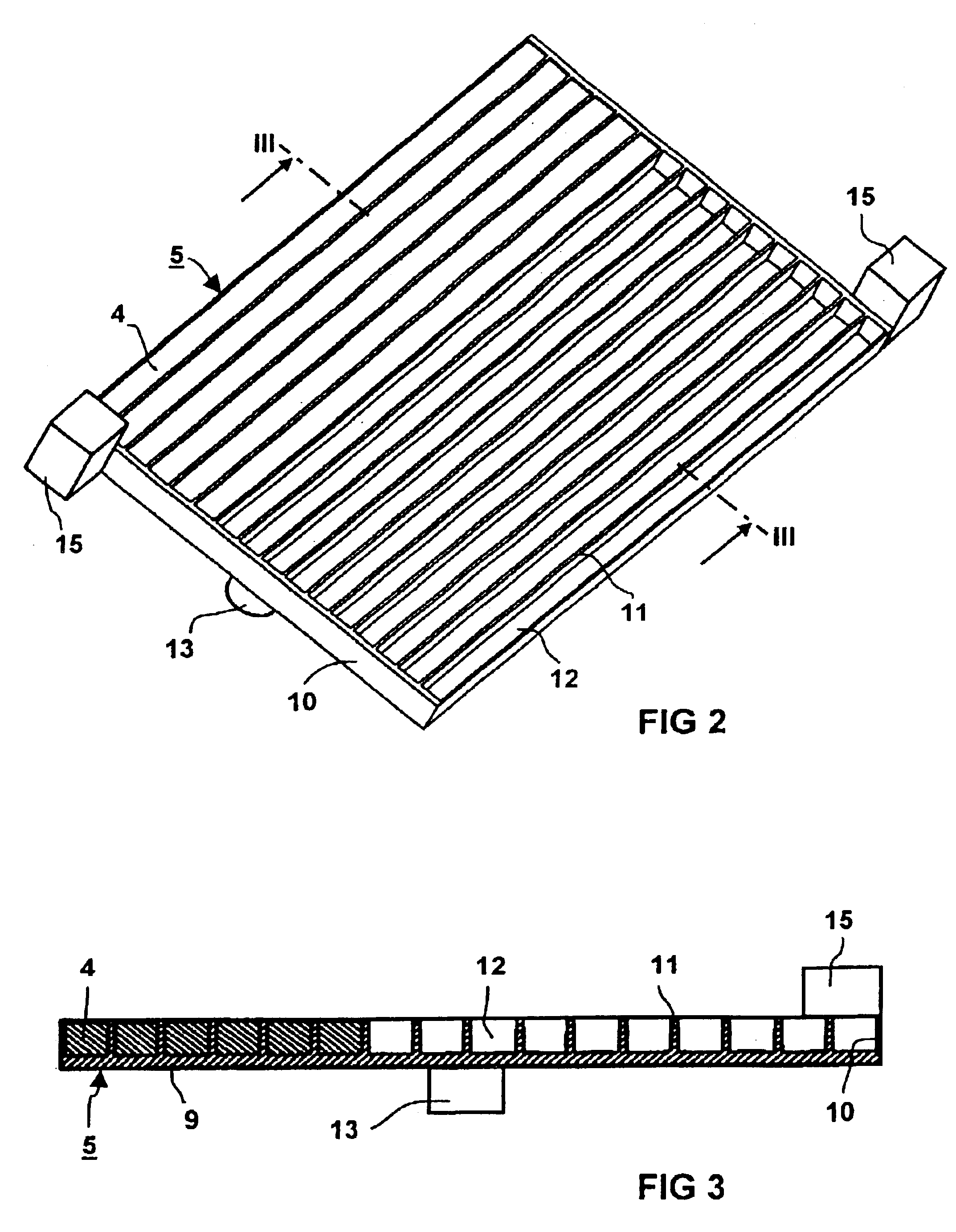
[0030]As can be seen from FIG. 2 in conjunction with FIG. 3, the reflector part 5 has a base plate 9, on which a frame-shaped boundary wall 10 is fitted.

[0031]The space surrounded by the boundary wall 10 is subdivided into a number of compartments, one of which is provided with the reference symbol 12, by partitions 11 running parallel to one another and parallel to two mutually opposite sections of the boundary wall 10.

[0032]The compartments 12 each receive a rod-shaped scintillator 4 which is adhesively bonded into the respective compartment 12.

[0033]The dimensions of the scintillators 4 are coordinate...


PUM


Abstract

A radiation detector has a photodiode arrangement, a number of scintillators, and a reflector part having a number of compartments corresponding to the number of scintillators, which receive the scintillators in such a way that the scintillators are surrounded by walls of the compartments with the exception of their side respectively facing the photodiode arrangement.

Description

BACKGROUND OF THE INVENTION[0001]1. Field of the Invention[0002]The present invention relates to a radiation detector of the type having a number of scintillators which emit light when radiation to be detected is incident thereon, the light being detected by photodiodes of a photodiode arrangement.[0003]2. Description of the Prior Art[0004]Radiation detectors of the above type are used in computed tomography systems, for example. If X-ray quanta are incident on the scintillators, which are composed of a suitable luminescent material, for example luminescent ceramic, the X-ray quanta are converted into light quanta. The light quanta are converted by the photodiodes into an electric current corresponding to the intensity of the light, and this current is amplified by an electronic unit and converted into digital data which are processed to form X-ray images by means of a computer associated with the computer tomography system.[0005]In order to obtain a maximum light yield on the photo...

Claims


Application Information

Patent Timeline
Patent Type & Authority Patents(United States)
IPC IPC(8): G01T1/20G01T1/202G01T1/00H01L31/09
CPCG01T1/202G01T1/2018G01T1/20183G01T1/20182
Inventor FREUND, ANDREASLEPPERT, JURGEN
Owner SIEMENS HEALTHCARE GMBH
Learn More