Angle of rotation sensor

a technology of rotation sensor and angle, applied in the field of position sensor, can solve the problems of insufficient mechanical complexity of gears, insufficient for many application purposes, and inability to detect only an angular range of 0° to 360°, and achieve the effect of high resolving power

Inactive Publication Date: 2005-05-17
TECH3 E K
View PDF22 Cites 48 Cited by
  • Summary
  • Abstract
  • Description
  • Claims
  • Application Information

AI Technical Summary

Benefits of technology

[0009]Embodiments of the present invention improve the angle of rotation sensor of the type mentioned in the introduction such that it operates with high resolving power in a measurement range of more than 360° and especially of several full rotations.
[0011]A principle of the invention is to also move the shaft, whose angle of rotation is to be measured, in the axial direction along a guide track as the shaft rotates about its axis, so that the distance between a magnet and sensor changes during rotation according to the pitch of the guide track. In this way, the amplitude of the sensor output signal changes, which produces a signal from which the number of full rotations completed by the shaft can be determined with sufficient accuracy. On the other hand, a precise signal for an angle in the range from 0° to 360° (e.g., excess rotation angle) can be determined within a full rotation from the sinusoidal and cosinusoidal signals, which is then added to the value of the number of full rotations times 360°.

Problems solved by technology

However, these sensors can detect only an angular range of 0° to 360°, which is insufficient for many application purposes.
In these cases, the mechanical complexity of the gears is relatively high.
In addition, flank errors and play in the gears cause measuring inaccuracies.
However, the latter sensors have less resolving power and thus measuring accuracy than the angle of rotation sensors mentioned in the introduction, which work with sinusoidal and cosinusoidal signals in the measurement range of 0° to 360°.

Method used


Image

  • Angle of rotation sensor
  • Angle of rotation sensor
  • Angle of rotation sensor

Examples


Embodiment Construction

[0024]This application claims priority of German application DE 103 34 869.7, filed Jul. 29, 2003, the entire disclosure of which is explicitly incorporated by reference.

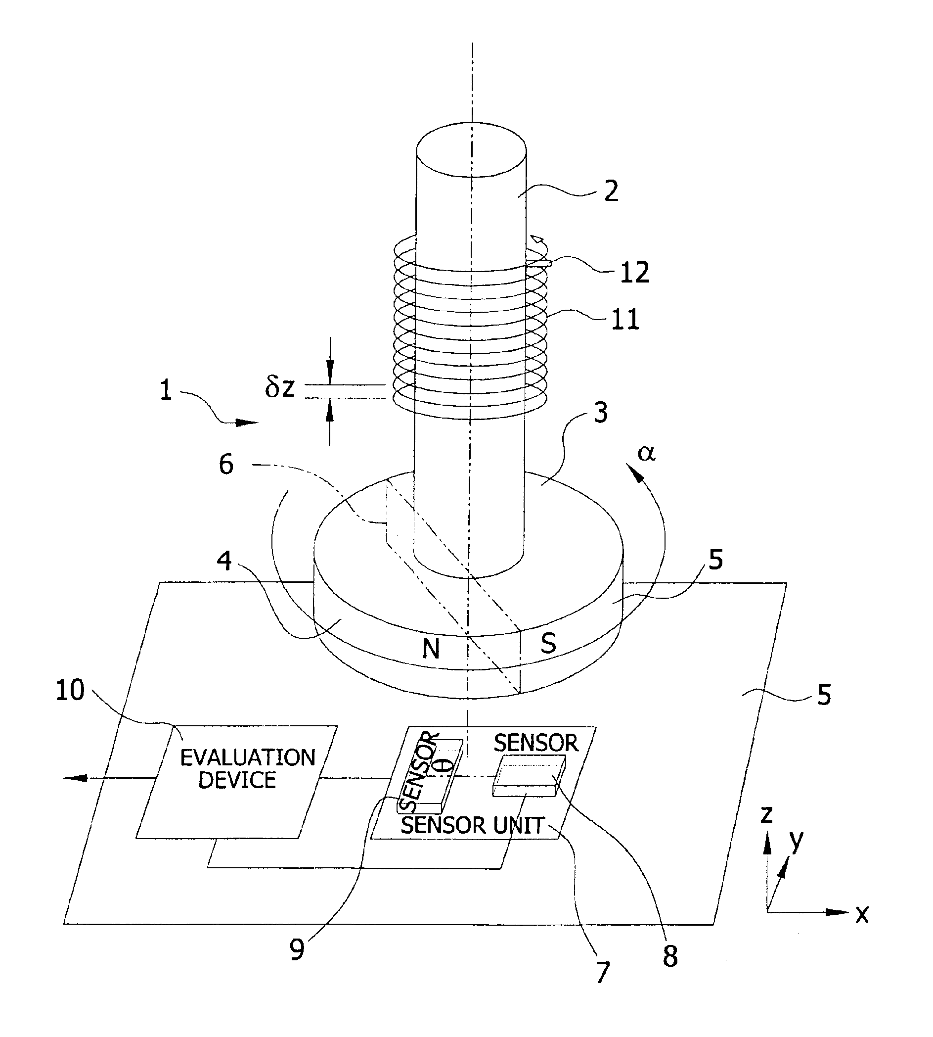
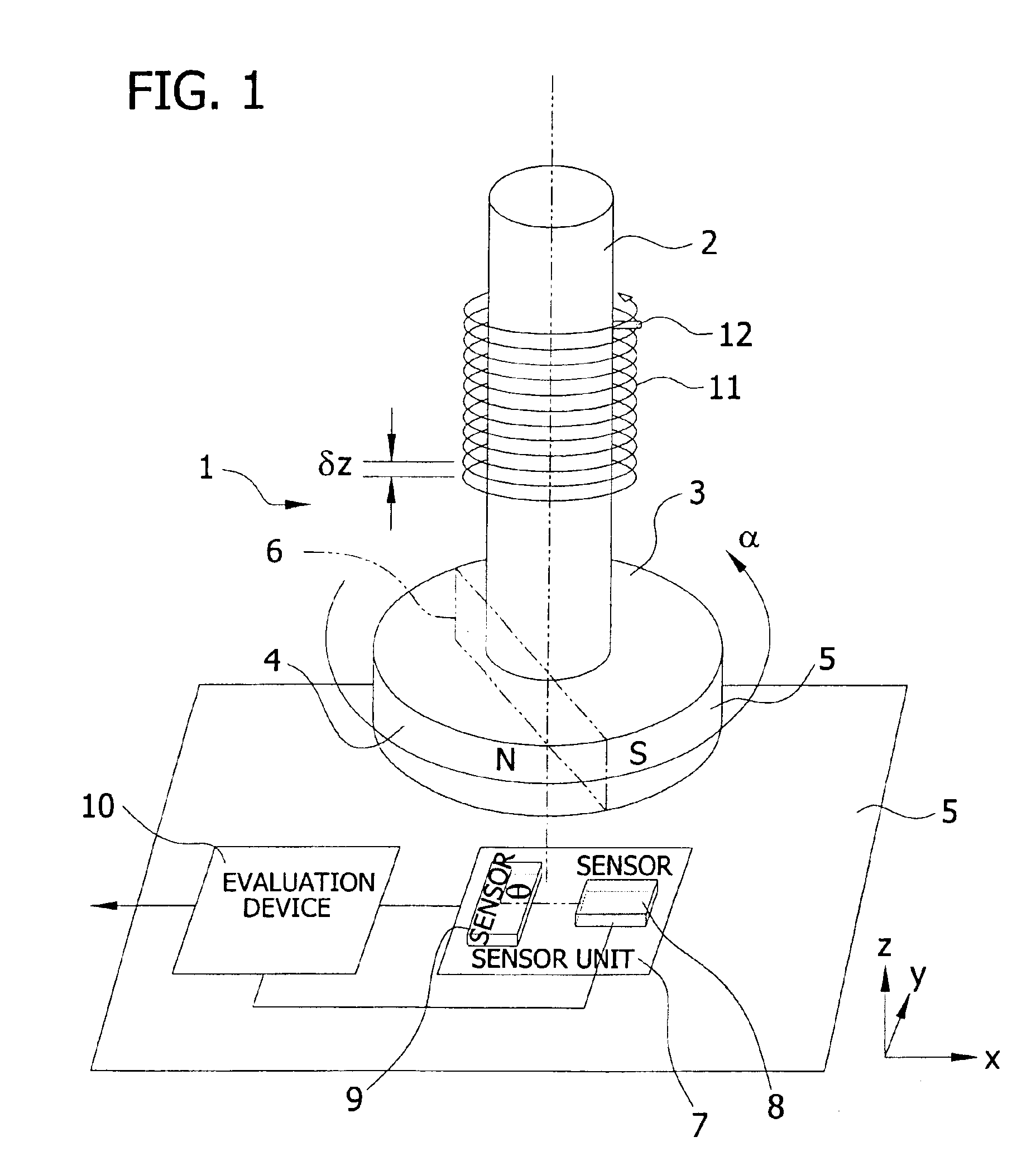
[0025]The angle of rotation sensor of FIG. 1 is designated in its entirety by the reference character 1. A magnet 3, which has a north pole 4 and a south pole 5, which are separated by an imaginary plane 6, which is parallel to the axis of rotation of the shaft 2, is mounted on a rotary shaft 2, whose angle of rotation a is to be measured. Opposite the magnet 3 there is a sensor unit 7, which contains two magnetic field-sensitive sensors 8 and 9, whose main directions of sensitivity are perpendicular to each other and lie in a plane (x-, y-plane) that is perpendicular to the center axis of the shaft 2. However, it should be mentioned that the two sensors 8 and 9 need not be perpendicular to each other in every case, but can also be aligned at a different angle φ to each other. The sensors 7 and 8 can lie next to eac...


PUM


Abstract

An angle of rotation sensor includes a rotary shaft coupled to a permanent magnet. A magnet-sensitive sensor element generates a sinusoidal output signal and a cosinusoidal output signal (Vx, Vy) as a function of the relative angle of rotation (a) between magnet and sensor element. Evaluation electronics generate from the output signals a signal corresponding to the angle of rotation. When the shaft rotates about its axis it moves linearly parallel to its axis along a guide track, and changes the distance between the magnet and sensor. From the sensor signals, a signal (B(z)) is determined, which corresponds to the magnitude of the field strength dependent on the distance. From this signal, a gross signal is determined, from which the number (n) of rotations can be determined. From the sinusoidal and cosinusoidal sensor signals, a fine signal is determined, which is added to the number of rotations multiplied by 360°.

Description

FIELD OF THE INVENTION[0001]The present invention relates to the field of position sensors. More specifically, the invention relates to an angle rotation sensor for detecting an angular position of a rotating element.BACKGROUND OF THE INVENTION[0002]An angle of rotation sensor is known from German Patent DE 197 47 753 C1. Here, a magnetic field sensor generates sinusoidal and cosinusoidal electrical output signals as a function of the relative rotary position between a magnet attached to a rotating shaft and the sensor. Similar angle of rotation sensors are also known from German Patents DE 195 39 134 A1, DE 44 22 868 A1, DE 41 00 666 A1, and DE 43 01 704 A1.[0003]However, these sensors can detect only an angular range of 0° to 360°, which is insufficient for many application purposes.[0004]German Patents DE 195 06 938 A1, DE 197 39 823 A1, and DE 199 62 241 A1 therefore propose to expand the measurement range to more than 360° and to couple two sensors by means of gears to the shaf...

Claims


Application Information

Patent Timeline
Patent Type & Authority Patents(United States)
IPC IPC(8): B62D15/02B62D15/00G01D5/14G01B7/30G01D5/16G01D5/12
CPCG01D5/145G01D2205/22G01D2205/26
Inventor KUNZ-VIZENETZ, THOMAS
Owner TECH3 E K
Why Eureka
Try Eureka