Image forming apparatus and developer replenishment control method

a technology of image forming apparatus and developer, applied in the direction of electrographic process apparatus, instruments, optics, etc., can solve the problems of image fogging of toner, slow charge rise, frequent occurrence of image fogging, etc., and achieve the effect of high-quality image formation

Inactive Publication Date: 2005-05-17
KK TOSHIBA +1
View PDF6 Cites 5 Cited by
  • Summary
  • Abstract
  • Description
  • Claims
  • Application Information

AI Technical Summary

Benefits of technology

[0011]The object of the present invention is to provide an image forming apparatus and a developer replenishment control method, which are capable of performing high-quality image formation in any environment after release of a forcible toner replenishment mode.

Problems solved by technology

In a high-humidity environment, however, there arises such a problem that when toner is supplied to the developer, the rise in charge becomes slower than in a normal-humidity or low-humidity environment due to moisture-absorption of the toner (developer) itself.
If image formation is performed in the state in which the supplied toner is not sufficiently charged, image fogging of the toner occurs.
In such a case, even when the forcible toner replenishment mode is finished and the normal mode is restored, the charge amount (level) of the developer is still lower than in the normal state and the replenishment of recycled toner results in frequent occurrence of image fogging.

Method used


Image

  • Image forming apparatus and developer replenishment control method
  • Image forming apparatus and developer replenishment control method
  • Image forming apparatus and developer replenishment control method

Examples


first embodiment

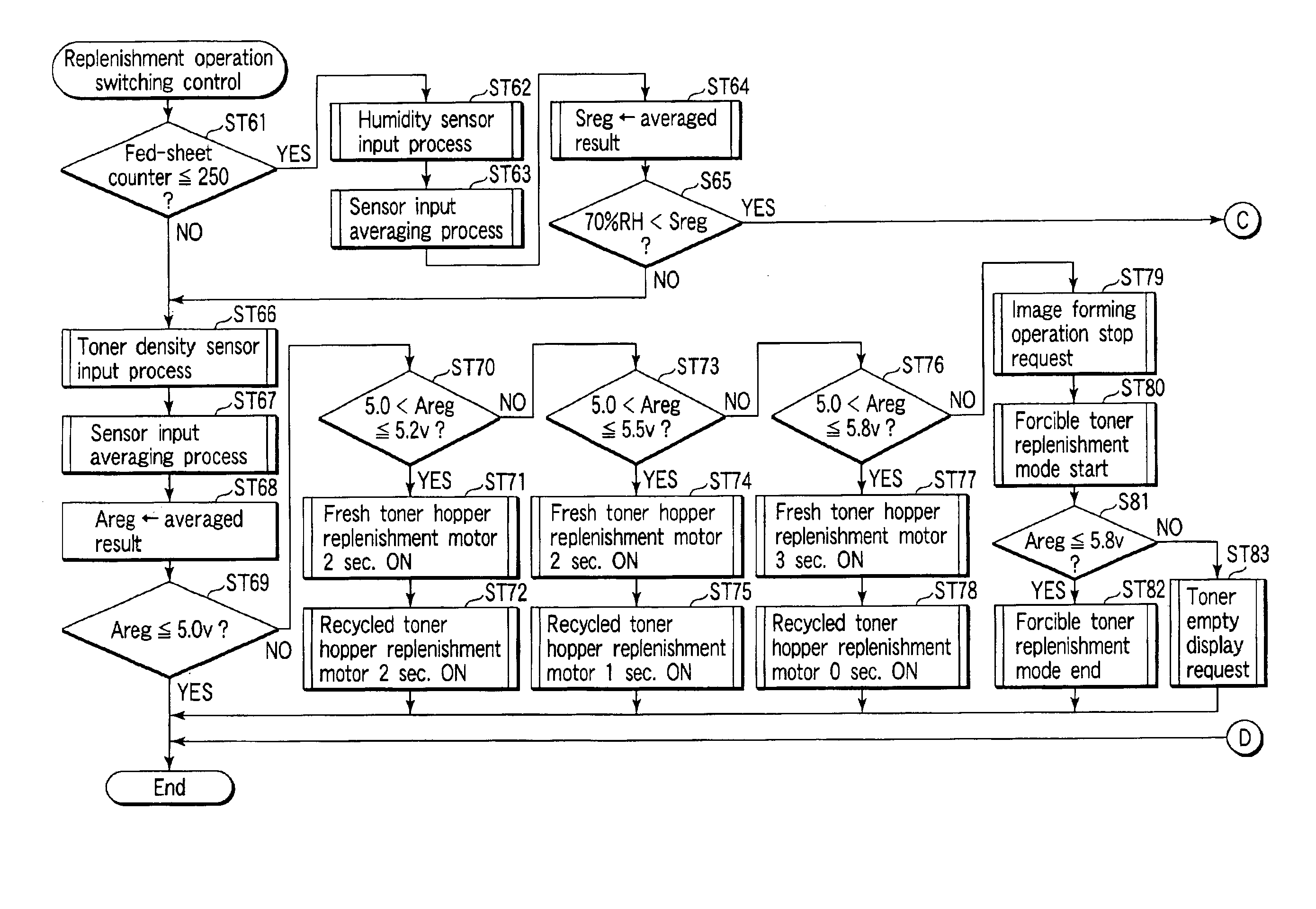
[0104]The toner replenishment operation switching control in the present invention will now be described with reference to the flowcharts of FIG. 14 and FIG. 15.

[0105]When the forcible toner replenishment mode is released, the printer CPU 110 confirms the count value of the counter 115a (ST21).

[0106]If the count value of the counter 115a is “250” (number of sheets fed) or more, the printer CPU 110 performs the toner density sensor input process in connection with the input from the toner density sensor 17 (ST22). The printer CPU 110 averages the input value from the toner density sensor 17 (ST23) and temporarily stores (Areg) the averaged result (ST24).

[0107]The printer CPU 110 determines whether the temporarily stored averaged result is equal to or less than 5.0 V (ST25). If it is equal to or less than 5.0 V, the printer CPU 110 finishes the replenishment operation switching control.

[0108]If the temporarily stored averaged value is greater than 5.0 V in step ST25, the printer CPU 1...

second embodiment

[0121]the present invention will now be described.

[0122]In the first embodiment, after the release of the forcible toner replenishment mode, in the image forming operation in any environment, the recycled toner replenishment is stopped and only the fresh toner is replenished until a predetermined number of sheets are fed. Thereby, the probability of the occurrence of image fogging is reduced.

[0123]However, in the high-humidity environment, image fogging occurs frequently and recycled toner cannot effectively be used as in the normal-humidity or low-humidity environment.

[0124]In the second embodiment, the humidity sensor 55 attached to the machine detects the environmental condition (humidity) of the machine. The replenishment of recycled toner in the image forming operation after the release of the forcible toner replenishment mode can be varied in accordance with the detection level indicated by the humidity sensor 55.

[0125]Toner replenishment operation switching control according ...


PUM


Abstract

After a toner empty state, toner is filled. Following the filling of toner, a forcible toner replenishment mode is performed. After release of the forcible toner replenishment mode, a printer CPU replenishes only fresh toner and does not replenish recycled toner while image formation is performed on a predetermined number of paper sheets or while a developing device is driven for a predetermined time.

Description

CROSS-REFERENCE TO RELATED APPLICATIONS[0001]This application is based upon and claims the benefit of priority from the prior Japanese Patent Application No. 2002-128879, filed Apr. 30, 2002, the entire contents of which are incorporated herein by reference.BACKGROUND OF THE INVENTION[0002]1. Field of the Invention[0003]The present invention relates to an image forming apparatus, such as a digital copying machine, which forms, by making use of an electrophotographic process, an image on a fed paper sheet.[0004]2. Description of the Related Art[0005]A conventional image forming apparatus using an electrophotographic process, for example, a digital copying machine, includes an image forming section which forms an image based on image data and outputs the image onto a recording medium such as paper.[0006]The image forming apparatus has a photosensitive drum that carries thereon an electrostatic latent image corresponding to the image data. The image forming apparatus includes a charger...

Claims


Application Information

Patent Timeline
Patent Type & Authority Patents(United States)
IPC IPC(8): G03G15/08G03G21/10
CPCG03G21/105G03G15/0855G03G15/0891G03G15/0848
Inventor KATOH, TETSUOKUROYAMA, KOICHI
Owner KK TOSHIBA
Why Eureka
Try Eureka