Image forming apparatus

a technology of image forming apparatus and forming section, which is applied in the direction of electrographic process apparatus, thin material processing, instruments, etc., can solve the problems of paper jamming or damage, the color image forming apparatus provided with the single image forming section cannot fully satisfy the consumer's needs for faster black-and-white image forming processes, and the speed limit of the image forming process

Active Publication Date: 2007-09-27
SHARP KK
View PDF3 Cites 1 Cited by
  • Summary
  • Abstract
  • Description
  • Claims
  • Application Information

AI Technical Summary

Benefits of technology

[0009]A feature of the invention is to provide an image forming apparatus that has a plurality of image forming sections, a paper feeding section, and a paper output section, arranged in such a manner as to render paper transport paths as simple as possible, thereby enabling both fast black-and-white image formation and high-quality color image formation.

Problems solved by technology

In order to obtain a high-quality color image without any out-of-register colors, there is a limit to speed of image forming process.
Thus, the color image forming apparatus provided with the single image forming section cannot fully satisfy consumer needs for faster black-and-white image forming processes.
However, no conventional apparatus including the one disclosed in JP H10-086455A has a plurality of image forming sections, a paper feeding section, and a paper output section, arranged so as to form a shortest paper transport path.
The bend in the transport path for paper on which an image is formed in the second image forming section to be transported on is likely to cause paper to be jammed or damaged.
Thus, the conventional apparatus cannot provide both of fast black-and-white image forming processes and high-quality color image forming processes.
This problem also occurs in an image forming apparatus, of other type than an electrophotographic image forming apparatus, such as an inkjet image forming apparatus, that is provided with a plurality of image forming sections.

Method used


Image

  • Image forming apparatus
  • Image forming apparatus
  • Image forming apparatus

Examples


first embodiment

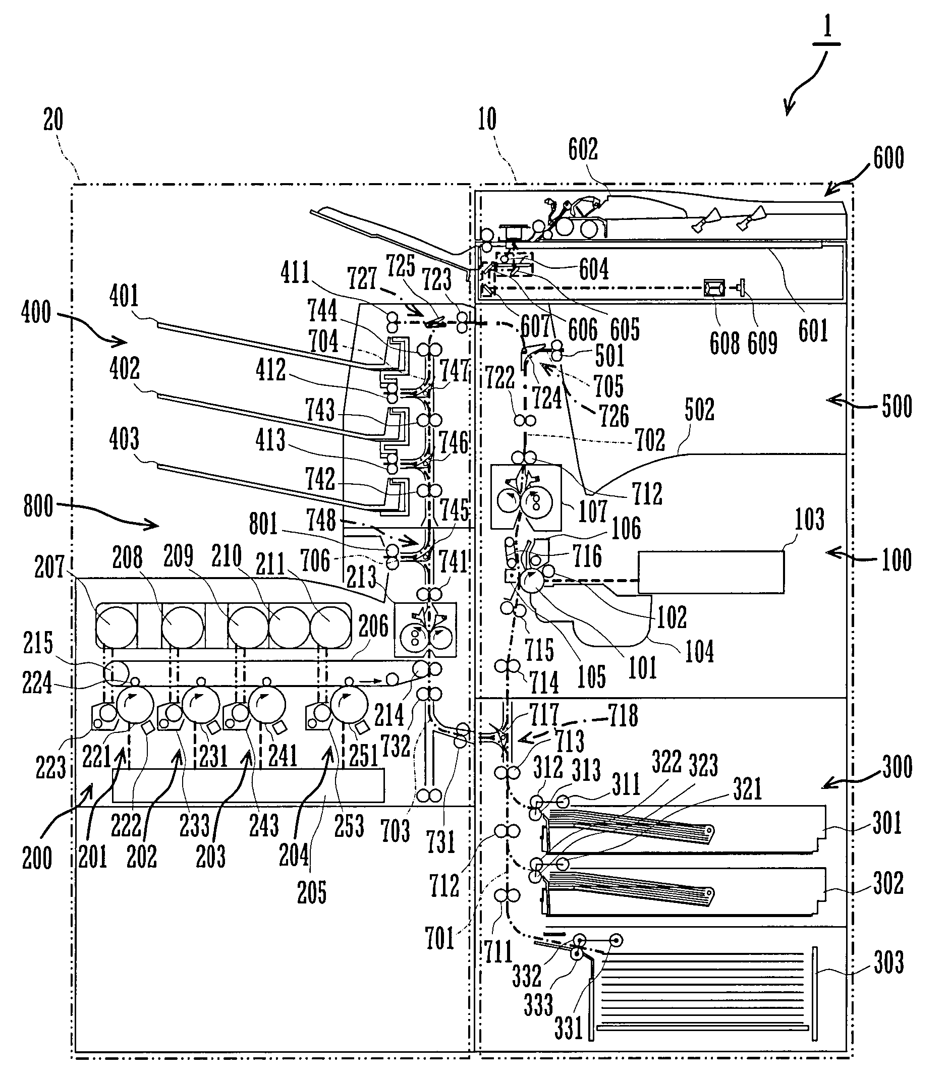
[0016]With reference to the accompanying drawings, preferred embodiments of the invention will be described below. FIG. 1 is a vertical cross-section of an image forming apparatus 1 according to the invention. The apparatus 1 includes a first image forming section 100, a second image forming section 200, a paper feeding section 300, a first paper output section 400, a second paper output section 500, a scanner section 600, and a switchback section 800. The apparatus 1 also has first to sixth transport paths 701 to 706 formed therein.

[0017]The first path 701 is formed between the section 300 and the section 100. The second path 702, connected to the path 701, is formed between the section 100 and the section 400. The third path 703 is formed between a midway point of the path 701 and the section 200. The fourth path 704, connected to the path 703, is formed between the section 200 and a midway point of the path 702. The fifth path 705 is formed between the midway point of the path 70...

second embodiment

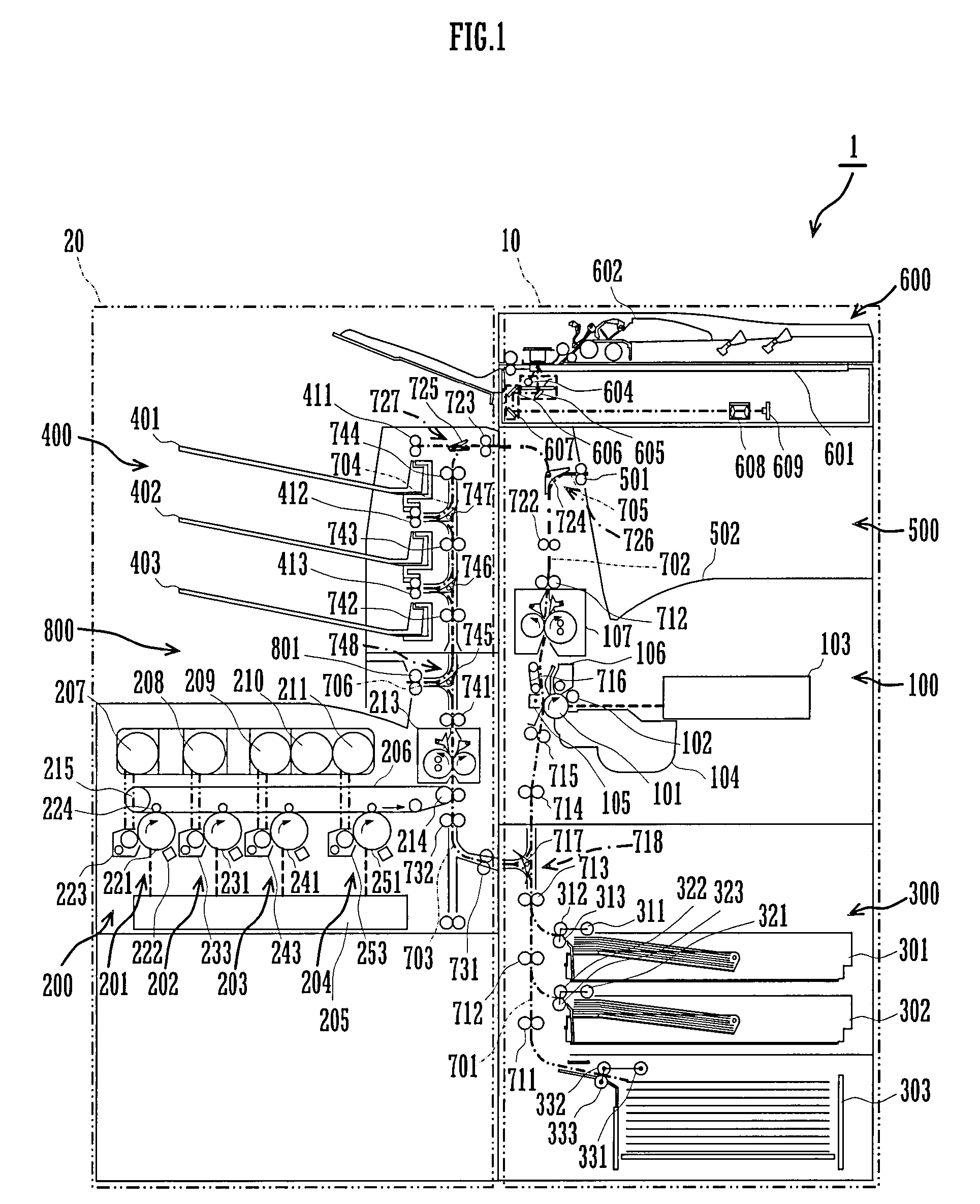
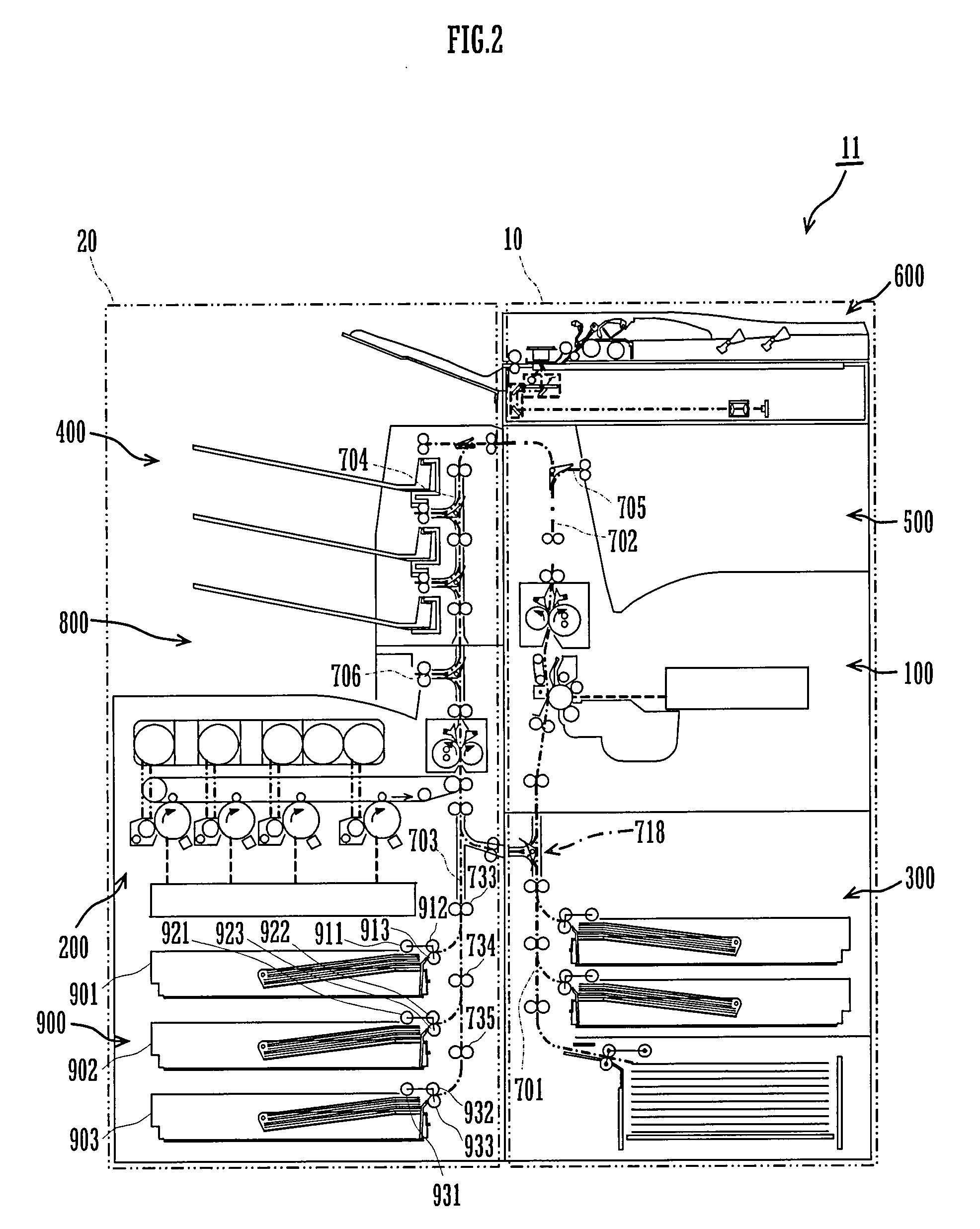
[0050]FIG. 2 is a vertical cross-section of an image forming apparatus 11 according to the invention. The apparatus 11 includes a second paper feeding section 900 in addition to the elements of the apparatus 1. The section 900 is arranged below the second image forming section 200 in the left-side portion 20.

[0051]The section 200 is a tandem-type color image forming section that has four photoreceptor drums 221, 231, 241, and 251 horizontally aligned with one another, and is short in height. Thus, there is sufficient space below the section 200 for positioning the section 900. Besides the section 900, the apparatus 11 has the path 703 extended downward, and transport rollers 733 to735.

[0052]The section 900 has three-tier paper cassettes 901 to 903, pick-up rollers 911, 921, and 931, feeding rollers 912, 922, and 932, and friction rollers 913, 923, and 933. Each of the cassettes 901 to 903 stores therein a plurality of sheets of paper of a single size.

[0053]Rotation of the rollers 91...

third embodiment

[0055]FIG. 3 is a vertical cross-section of an image forming apparatus 21 according to the invention. The apparatus 21 includes a vertically downsized version of the paper output section 500 provided in the apparatus 11. Despite a decreased capacity of the section 500, the apparatus 21 has a shorter paper transport distance from the section 200 to either one of the sections 400 and 800 through the paths 702, 704, and 706.


PUM


Abstract

An image forming apparatus includes a first and a second image forming sections, a paper feeding section, and a paper output section. The image forming sections form an image on paper independently. The apparatus is laterally dividable into a first and a second portions where the first and second image forming sections are respectively positioned. The feeding section is arranged below the first image forming section in the first portion. The output section is arranged above the second image forming section in the second portion. The apparatus has two simple transport paths that run vertically through the image forming sections, respectively, without intersecting each other and detouring around the second or first image forming section.

Description

CROSS REFERENCE[0001]This Nonprovisional application claims priority under 35 U.S.C. §119(a) on Patent Application No. 2006-083645 filed in Japan on Mar. 24, 2006, the entire contents of which are hereby incorporated by reference.BACKGROUND OF THE INVENTION[0002]The invention relates to an image forming apparatus that includes a first image forming section, a second image forming section, a paper feeding section for feeding paper to each of the first and second image forming sections, and a paper output section for outputting paper on which an image is formed in each of the first and second sections.[0003]As a type of electrophotographic image forming apparatus, a color image forming apparatus is known that is provided with a single image forming section that has toner of four colors, i.e., three subtractive primary colors and black, stored therein and performs both black-and-white and color image forming processes. In a color image forming process, this apparatus superimposes toner...

Claims


Application Information

Patent Timeline
Patent Type & Authority Applications(United States)
IPC IPC(8): G03G15/00
CPCG03G15/6529G03G21/1695G03G2215/00021
Inventor TSUCHIDA, MASAMI
Owner SHARP KK
Why Eureka
Try Eureka