Portable Shippable Facilities

Inactive Publication Date: 2008-10-23
GUILD ASSOCS
View PDF35 Cites 43 Cited by
  • Summary
  • Abstract
  • Description
  • Claims
  • Application Information

AI Technical Summary

Benefits of technology

[0003]There is a need for a portable facility system which can be easily shipped to a site of deployment, quickly set into operation, withstand various harsh envi

Problems solved by technology

Setting up the temporary structures is difficult, time consuming and the resulting structures are not necessarily ideal for the task given the war/disaster environme

Method used


Image

  • Portable Shippable Facilities
  • Portable Shippable Facilities
  • Portable Shippable Facilities

Examples


Embodiment Construction

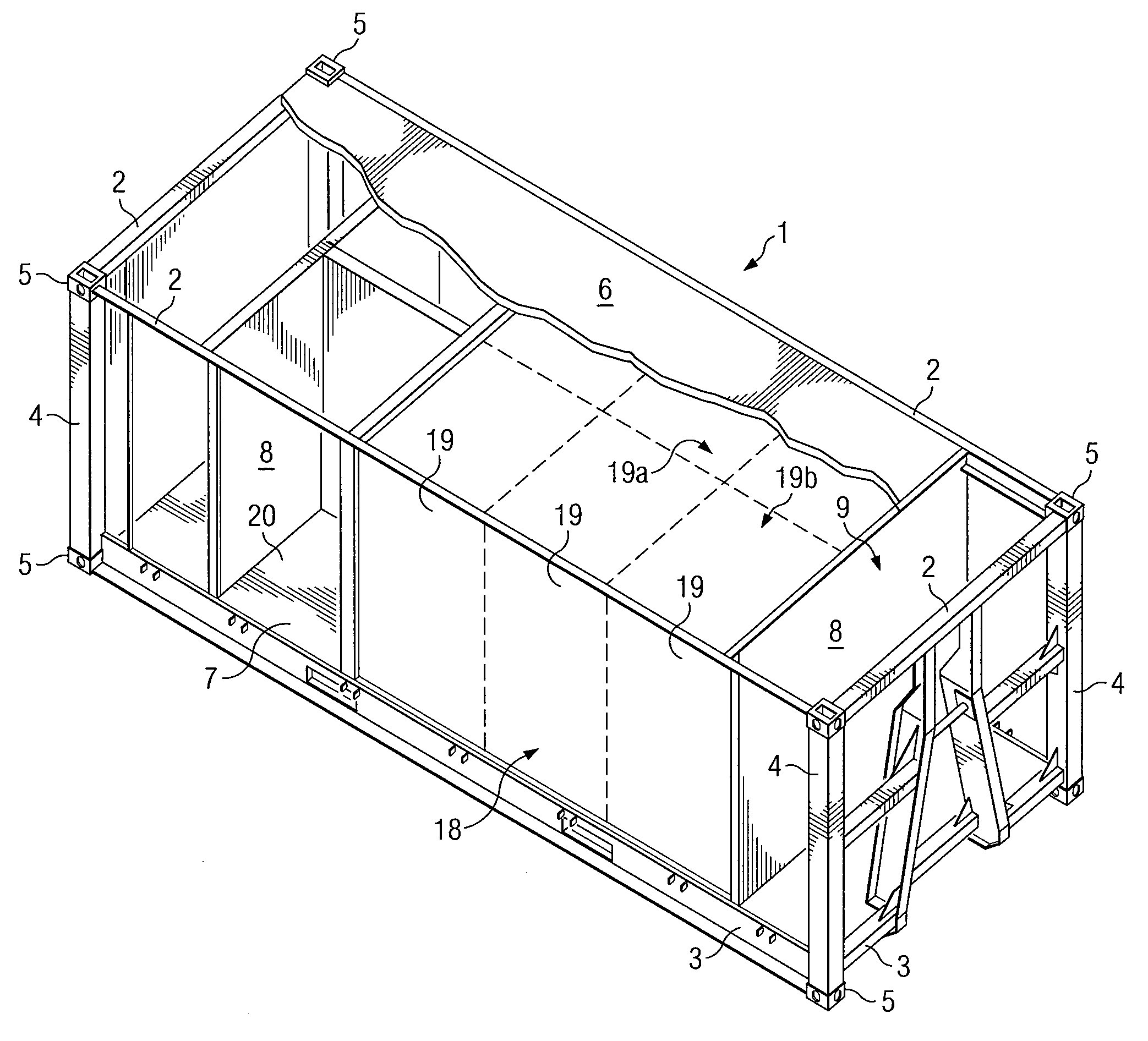
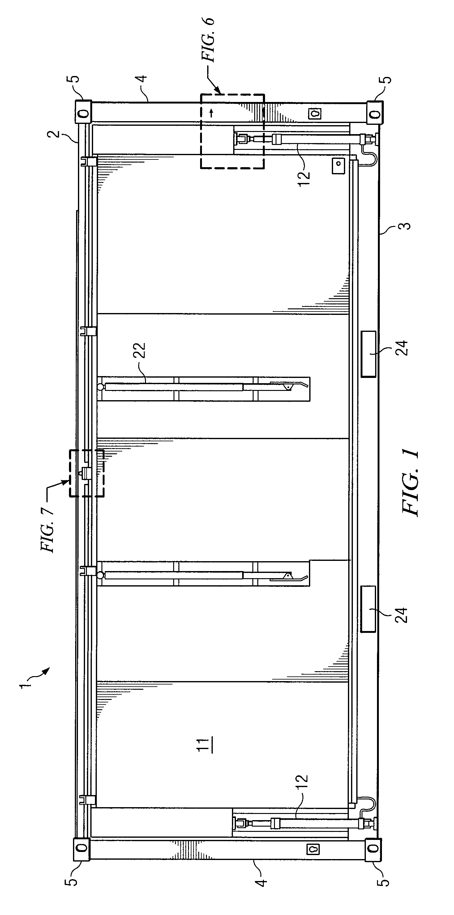
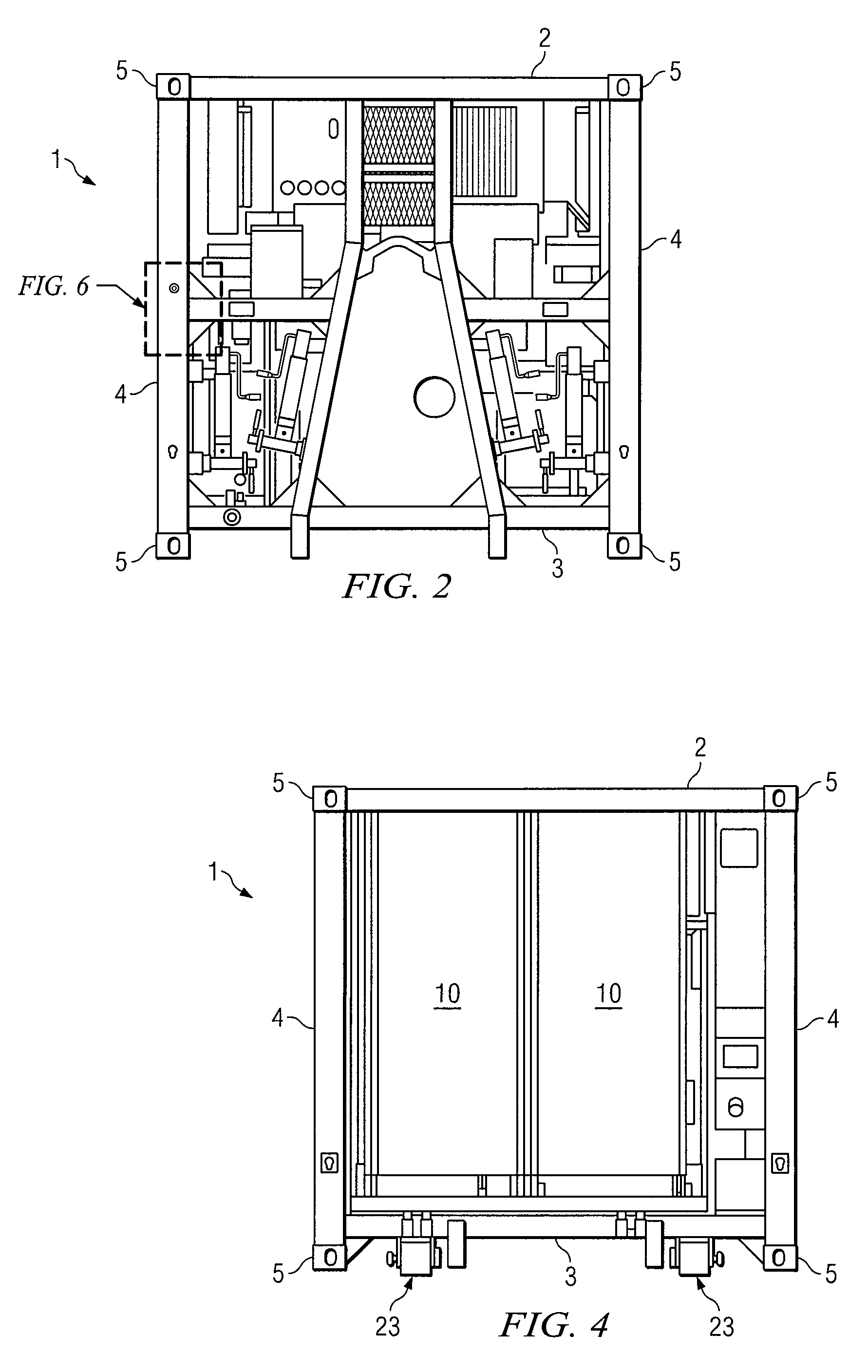
[0032]The invention is directed to portable facilities, preferably shippable facilities e.g., portable facility 1, shippable via standard methodologies. Preferably, the portable facility, according to one embodiment of the invention, may comprise a frame structure, e.g., a rectangular or a square shaped frame structure. For example, and preferably according to an embodiment, referring to FIGS. 1, 2 and 3, the frame structure may comprise four top rails 2, four bottom rails 3 (according to some embodiments eight bottom rails), and four end rails or corner rails 4. The top 2 and bottom rails 3 may be connected together via the end or corner rails 4 extending between top rails 2 and bottom rails 3. The location at the juncture of the top rails 2 and end / corner rails 4 may preferably include standard corner fittings 5, e.g., as known in the art by persons of ordinary skill in the shipping container industry. In addition, and preferably according to an embodiment, at the location of the ...


PUM


Abstract

The present invention provides a portable shippable morgue system. The system may comprise (1) bottom, top and corner rails, and (2) corner fittings. Corner rails extend between bottom and top rails and connect them together to form a square and/or rectangular shaped frame. Bottom rails may include forklift engagement areas. Corner fittings are located at the connection point of the vertical corner rails and top rails. A top is positioned between the top rails and a bottom is positioned between the bottom rails. Vertically opposed end walls may be positioned between the top and bottom rails. The invention provides first and second spaced apart opposed vertical platforms, each in abutting engagement or engageable with a top rail and a bottom rail. The invention further provides a remains storage unit.

Description

FIELD OF THE INVENTION[0001]The invention relates to portable facilities, namely shippable facilities that are portable via standardized shipping methodologies and expand to provide full use.BACKGROUND OF THE INVENTION[0002]During times of war, soldiers and / or temporary deployment teams of workers / volunteers are sent into the areas without suitable facilities. These teams, often enlisted soldiers or national guardsman, arrive at a war and / or disaster site and are tasked with a variety of projects but may first be required to build or otherwise deploy living facilities, such as showers and / or latrines often located a substantial geographic distance from their home base, e.g., the distance between Iraq and the United States. Presently, these teams / soldiers set up tent structures or more rigid structures on site. Teams must set up facilities including the running of utilities, e.g., water and electricity, to the newly set up structures, e.g., tents. Setting up the temporary structures ...

Claims


Application Information

Patent Timeline
IPC IPC(8): E04H9/00E04B1/00
CPCE04B1/3444
Inventor BERNS, HENRY C.CHURCH, DAVID L.
Owner GUILD ASSOCS
Why Eureka
Try Eureka