Developing unit

a technology of development unit and development unit, applied in the direction of electrographic process apparatus, instruments, optics, etc., can solve the problems of image failure, development is more likely to stagnate on the terminating end side than on the starting end side of the conveyance, and the circulation of the developer is more likely to be affected by image failure, so as to prevent the occurrence of image failure, prevent output ripples, and maximize the conveying force of each agitating elemen

Inactive Publication Date: 2009-12-22
SHARP KK
View PDF7 Cites 2 Cited by
  • Summary
  • Abstract
  • Description
  • Claims
  • Application Information

AI Technical Summary

Benefits of technology

[0011]The present invention has been devised in view of the above conventional problems, it is therefore an object of the present invention to provide a developing unit with a simple configuration, which permits the developer in a developer hopper to be agitated and conveyed highly efficiently so as to achieve good circulation of the developer and can realize high-quality image formation upon high-speed printing without causing any imbalance in developer distribution.

Problems solved by technology

However, in the conventional developing unit, for example in a case where the developer is conveyed whilst being agitated with a screw etc., the developer is more likely to stagnate on the terminating end side than on the starting end side of conveyance.
Accordingly, the quantity distribution of the developer inside the developer hopper becomes imbalance, or the developer tends to gather to the downstream side with respect to the direction of conveyance, causing image failures if high-speed printing is performed.
Also, since conveyance of the developer inside the developer hopper by the agitating and conveying means suffers the problem that exchange of the developer to be conveyed cannot be reliably and smoothly done, hence circulation of the developer becomes poor and the efficiency of conveyance lowers, this configuration faces difficulties in dealing with the recent high-speed trend of image output.
However, the above-described conventional configuration not only needs a greater number of apparatus components but also increases complexity in machine structure, hence suffers difficulties in achieving space-saving.

Method used


Image

  • Developing unit
  • Developing unit
  • Developing unit

Examples


Embodiment Construction

[0048]The best mode for carrying out the present invention will be described with reference to the drawings.

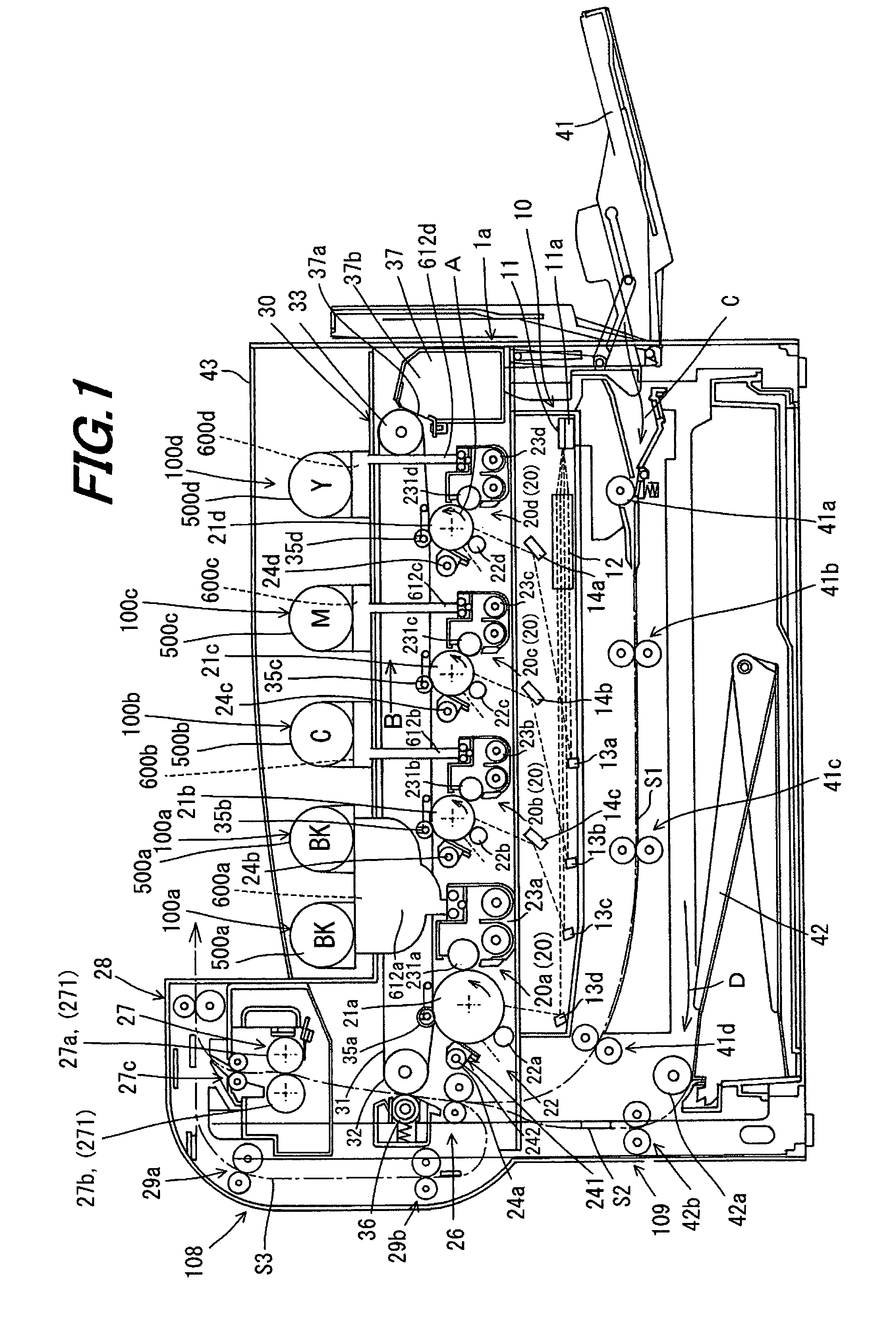
[0049]FIG. 1 is an example of the mode for carrying out the present invention, and is an illustrative view showing an overall configuration of an image forming apparatus adopting a developing unit according to the present invention.

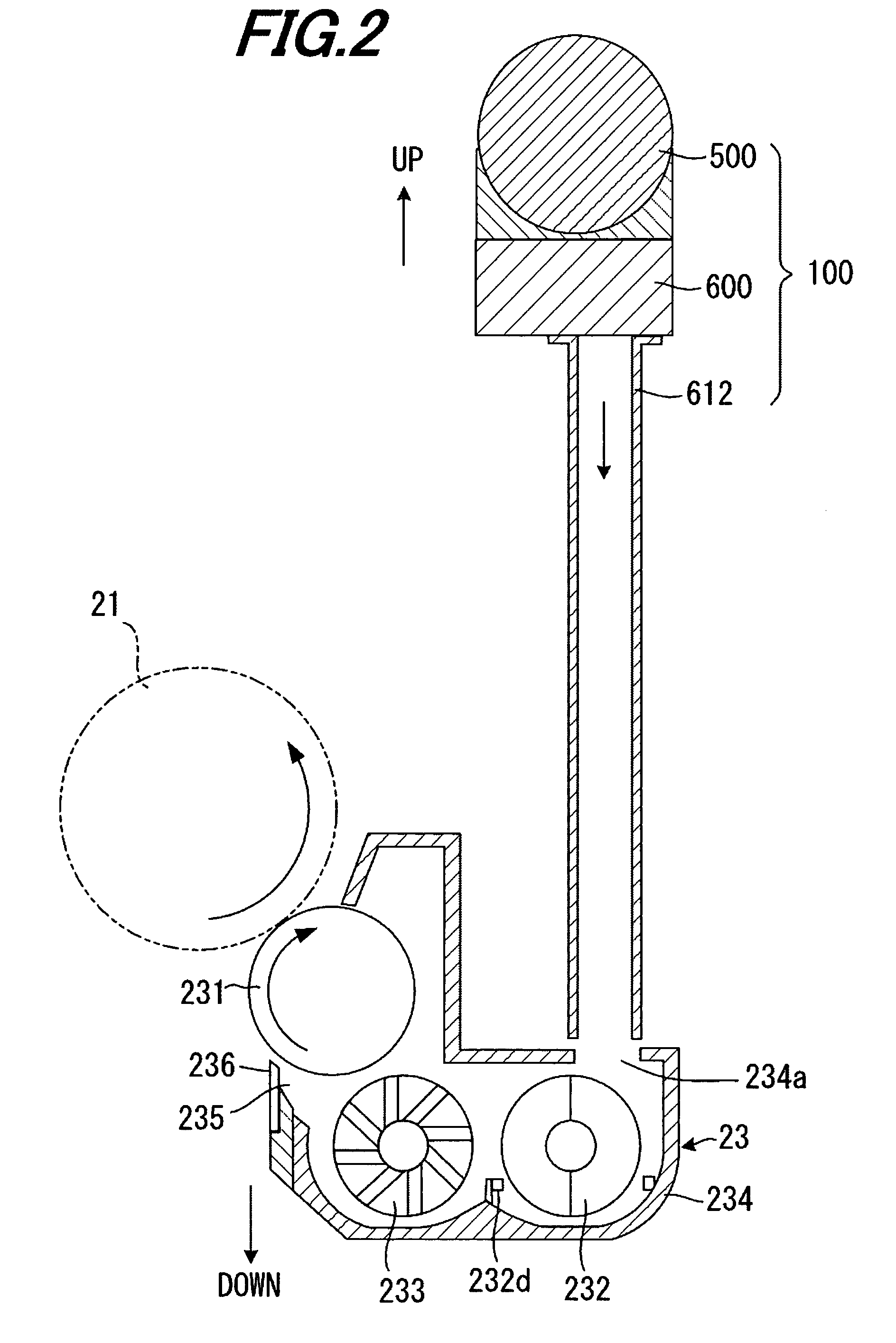
[0050]As shown in FIG. 1, the present embodiment is a developing unit 23 (23a, 23b, 23c or 23d) for use in an image forming apparatus 1 in which developer images are formed with developers (including toners) supplied from developing rollers 231 (231a, 231b, 231c and 231d) on photo receptor drums 21 (21a, 21b, 21c and 21d) in accordance with image data and transferred to a recording sheet by a transfer process, and each developing unit 23 includes a toner bottle 200 (200a, 200b, 200c or 200d: FIG. 3) for storing toner and a toner supply device 100 (100a, 100b, 100c or 100d) for supplying toner to developing unit 23 so as to perform image output by au...


PUM


Abstract

A developing unit including: a first agitating and conveying rotor and second agitating and conveying rotor for agitating and conveying toner inside a casing; and a developing roller for supplying the toner to a photoreceptor drum is constructed such that the first agitating and conveying rotor has a rotary shaft arranged approximately parallel to the developing roller and a multiple number of agitating vanes arranged on the rotary shaft with an inclination to the axial direction of the rotary shaft; each agitating element is formed asymmetrically about a normal that passes through the rotational center and adjacent agitating elements are asymmetrical to each other; and an odd number of asymmetrical agitating elements are arranged alternately.

Description

[0001]This Nonprovisional application claims priority under 35 U.S.C. § 119(a) on Patent Application No. 2006-65624 filed in Japan on 10 Mar. 2006, the entire contents of which are hereby incorporated by reference.BACKGROUND OF THE INVENTION[0002](1) Field of the Invention[0003]The present invention relates to a developing unit, in particular relating to a developing unit for use in an image forming apparatus for performing image formation with toner.[0004](2) Description of the Prior Art[0005]Conventionally, in image forming apparatuses based on the electrophotography using toner, such as copiers, facsimile machines, etc., a developer is supplied as appropriate from a developing unit to an electrostatic latent image that is formed on a photoreceptor in accordance with image information so as to visualize it, and this developer image is in turn transferred to a recording medium to thereby achieve image output.[0006]Typically, the developer is comprised of a developer hopper for stor...

Claims


Application Information

Patent Timeline
Patent Type & Authority Patents(United States)
IPC IPC(8): G03G15/08
CPCG03G15/0872G03G2215/0833
Inventor KUNIHIRO, HISASHIOHGOSHI, TOSHIHIDE
Owner SHARP KK
Why Eureka
Try Eureka