Supercharge Your Innovation With Domain-Expert AI Agents!

Self-cleaning CPA device for high-debris applications

a technology of cpa devices and high-debris, which is applied in the direction of coupling devices, coupling bases/cases, electrical equipment, etc., can solve the problems of cpa devices that cannot be unmated, debris may accumulate around, and debris, such as mud, may accumulate on the connector, etc., to prevent the accumulation of debris

Inactive Publication Date: 2005-05-24
TE CONNECTIVITY CORP
View PDF12 Cites 25 Cited by
  • Summary
  • Abstract
  • Description
  • Claims
  • Application Information

AI Technical Summary

Benefits of technology

[0007]In accordance with at least one embodiment, multiple sweeping elements may be formed on the CPA with sloped surfaces extending laterally from either side of the CPA. The sloped surfaces may be formed at an acute or an obtuse angle with respect to one another. The CPA may also be provided with a blocking portion aligned to prevent debris from collecting under a latch assembly mounted to one of the first and second connector housings.
[0008]Certain embodiments of the present invention thus provide an electrical connector system that performs better in high-debris applications by removing debris and / or preventing accumulation of debris.

Problems solved by technology

In these applications, debris may accumulate on the connector when in the locked position.
More specifically, debris, such as mud, may accumulate around the resilient latch securing the connector halves together.
If the latch cannot be deflected, the connector halves cannot be unmated.
An operator in the field must then remove the debris from the connector, a process that consumes valuable time and may result in damage to the CPA, latch, or other connector components.
A secondary problem with conventional connectors is that the debris renders it more difficult to move the CPA.

Method used


Image

  • Self-cleaning CPA device for high-debris applications
  • Self-cleaning CPA device for high-debris applications
  • Self-cleaning CPA device for high-debris applications

Examples


Embodiment Construction

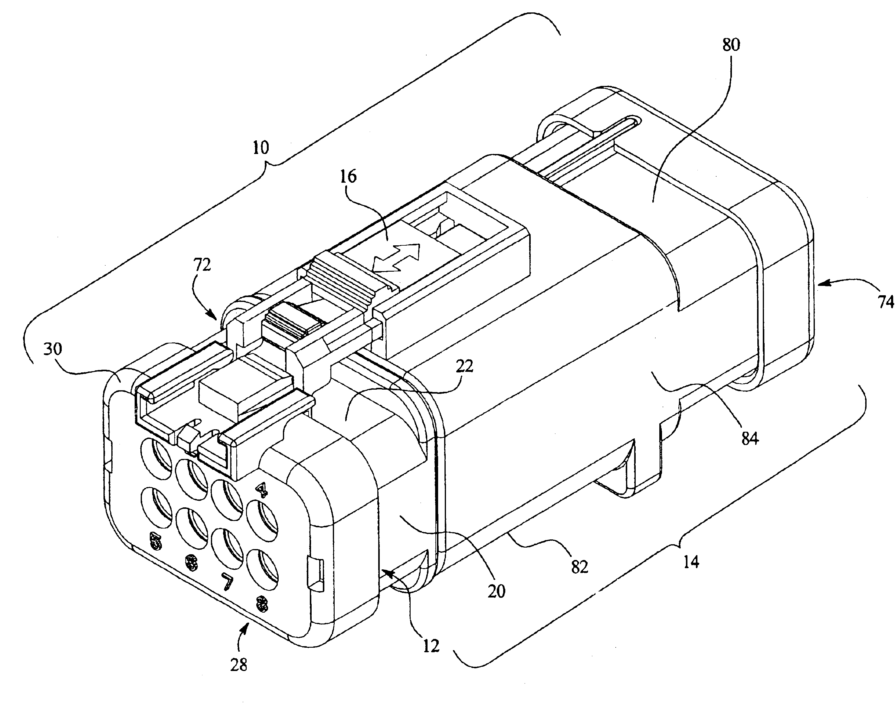
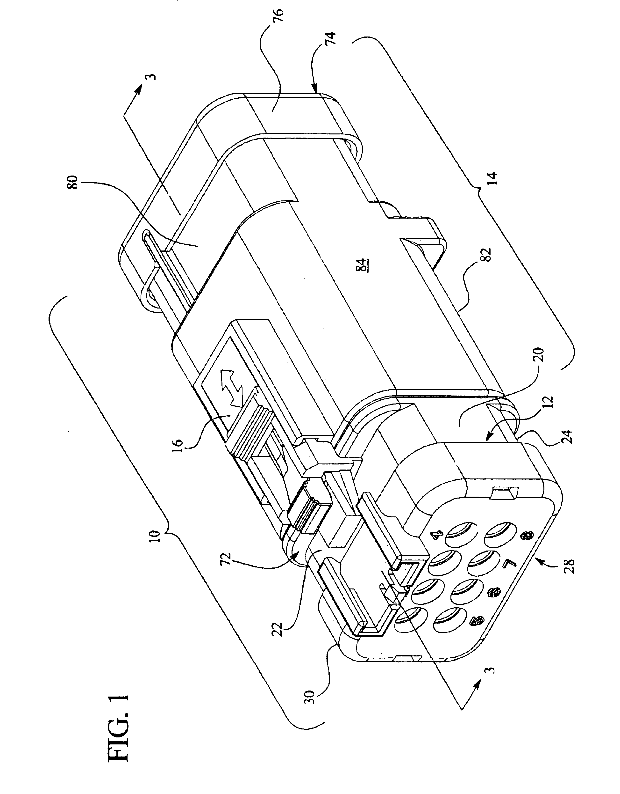
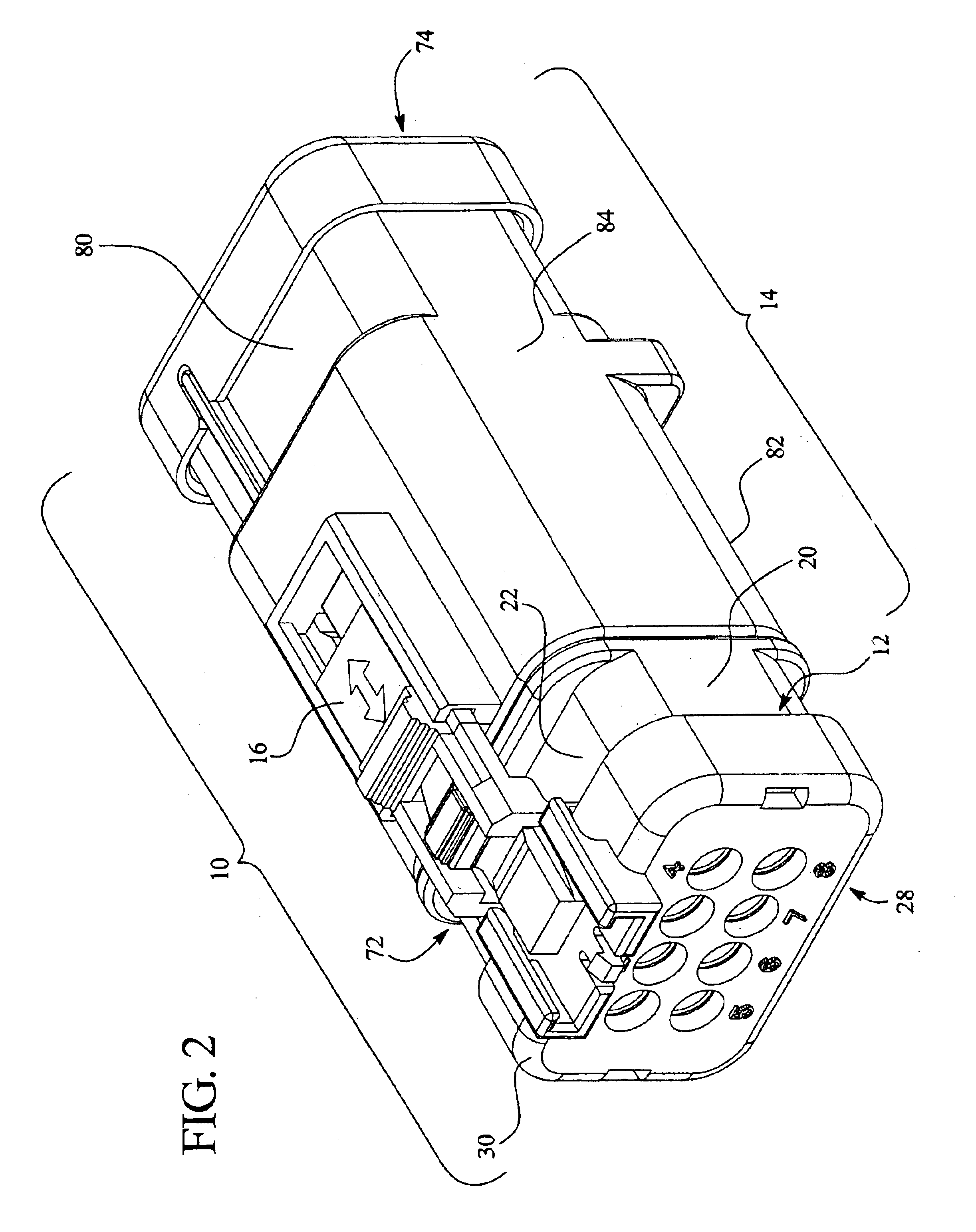
[0016]FIGS. 1 and 2 illustrate isometric views of a connector system 10. The connector system 10 includes a plug connector housing 12 that is mated to a cap connector housing 14. The connector system 10 also includes a connector position assurance device (CPA) 16 movable between locked and unlocked positions. In the locked position, as illustrated in FIG. 1, the CPA 16 indicates that the plug connector housing 12 and cap connector housing 14 are fully mated and prevents the separation of the mated plug and cap connector housings 12 and 14. In the unlocked position, illustrated in FIG. 2, the CPA 16 permits the separation of the plug and cap connector housings 12 and 14.

[0017]FIG. 3 illustrates a side sectional view taken along line 3—3 of FIG. 1, with the plug connector housing 12 and cap connector housing 14 mated, and the CPA 16 in the locked position. With reference to FIGS. 1-2, the plug connector housing 12 includes sides 20 joining a top portion 22 and a bottom portion 24. Als...


PUM


Abstract

An electrical connector assembly is provided, including a connector position assurance device (CPA) movable between locked and unlocked positions along a longitudinal axis of the CPA. The CPA includes rails. The connector assembly also includes first and second connector housings having mating ends configured to mate with one another. A CPA guide assembly is mounted to at least one of the first and second connector housings. The CPA guide assembly includes CPA guide rails slidably accepting the guide rail of the CPA. The CPA permits engagement and disengagement of the first and second connector housings when in the unlocked position. The CPA prevents disengagement of the first and second connector housings when in the locked position. When the first and second connector housings are disengaged, the CPA can not move to the locked position. The connector assembly further includes a sweeping element mounted to the CPA. The sweeping element is configured to extend laterally from the longitudinal axis of the CPA and positioned to provide a wedge to remove debris from the housing of the connector as the CPA is moved to the unlocked position. The debris builds up on the connector assembly while engaged and the CPA is locked. The removal of the debris occurs during movement of the CPA to the unlocked position because it is then that a connector latch should deflect to release the mating connector.

Description

BACKGROUND OF THE INVENTION[0001]Certain embodiments of the present invention generally relate to an electrical connector assembly that includes a self-cleaning connector position assurance device (CPA) that ensures matable connectable halves are fully mated with another.[0002]Connector devices have been proposed that provide electrical terminals having matable male to female connector halves. One of the male and female connector halves may include a resilient latch that locks behind a feature on the complementary connector half. When the connector halves are mated, a CPA is inserted to a locked position indicating that the connector halves are fully mated. The CPA is movable between a locked position indicating that the connector halves are mated and an unlocked position permitting unmating of the connector halves. An example of a connector assembly including a CPA may be found in U.S. Pat. No. 5,643,003. Some applications, however, require sealing to protect components from contam...

Claims


Application Information

Patent Timeline
IPC IPC(8): H01R13/639H01R13/627H01R13/52
CPCH01R13/52H01R13/639H01R13/6272
Inventor GRUBBS, JIMMY G.
Owner TE CONNECTIVITY CORP
Features
  • R&D
  • Intellectual Property
  • Life Sciences
  • Materials
  • Tech Scout
  • Unparalleled Data Quality
  • Higher Quality Content
  • 60% Fewer Hallucinations
Learn More