Nozzle design for high temperature attemperators

Active Publication Date: 2014-04-03
CONTROL COMPONENTS INC
View PDF29 Cites 10 Cited by
  • Summary
  • Abstract
  • Description
  • Claims
  • Application Information

AI Technical Summary

Benefits of technology

The nozzle assembly is designed to create a conical spray pattern with small droplet size. It includes a valve element that can be opened and closed to control fluid flow. When the valve is closed, cooling water is introduced into the nozzle and flows through the fluid chamber to the exterior of the nozzle assembly. The shape of the outflow opening and the nozzle cone effectively create a conical spray pattern. The design also includes a biasing spring that is protected from direct fluid flow and grooves to prevent debris accumulation in the central bore. The technical effect is a more precise and efficient spray pattern control with improved consistency.

Problems solved by technology

Because superheated steam can damage turbines or other downstream components, it is necessary to control the temperature of the steam.
One of the most commonly encountered problems in those systems integrating an attemperator is the addition of unwanted water to the steam line or pipe as a result of the improper operation of the attemperator, or the inability of the nozzle assembly of the attemperator to remain leak tight.
The failure of the attemperator to control the water flow injected into the steam pipe often results in damaged hardware and piping from thermal shock, and in severe cases has been known to erode piping elbows and other system components downstream of the attemperator.
Along these lines, water buildup can further cause erosion, thermal stresses, and / or stress corrosion cracking in the liner of the steam pipe that may lead to its structural failure.
In addition, the service requirements in many applications are extremely demanding on the attemperator itself, and often result in its failure.
More particularly, in many applications, various structural features of the attemperator, including the nozzle assembly thereof, will remain at elevated steam temperatures for extended periods without spray water flowing through it, and thus will be subjected to thermal shock when quenched by the relatively cool spray water.
Along these lines, typical failures include spring breakage in the nozzle assembly, and the sticking of the valve stem thereof.
Further, in probe style attemperators wherein the spray nozzle(s) reside in the steam flow, such cycling often results in fatigue and thermal cracks in critical components such as the nozzle holder and the nozzle itself.
Thermal cycling, as well as the high velocity head of the steam passing the attemperator, can also potentially lead to the loosening of the nozzle assembly which may result in an undesirable change in the orientation of its spray angle.
In addition, a streaming spray of cooling water will typically pass through the superheated steam flow and impact the interior wall or liner of the steam pipe, resulting in water buildup which is undesirable for the reasons set forth above.
Conversely, a non-uniform spray pattern of cooling water will result in an uneven and poorly controlled temperature reduction throughout the flow of the superheated steam.
Along these lines, the inability of the cooling water spray to efficiently evaporate in the superheated steam flow may also result in an accumulation of cooling water within the steam pipe.
The accumulation of this cooling water will eventually evaporate in a non-uniform heat exchange between the water and the superheated steam, resulting in a poorly controlled temperature reduction.

Method used


Image

  • Nozzle design for high temperature attemperators
  • Nozzle design for high temperature attemperators
  • Nozzle design for high temperature attemperators

Examples


first embodiment

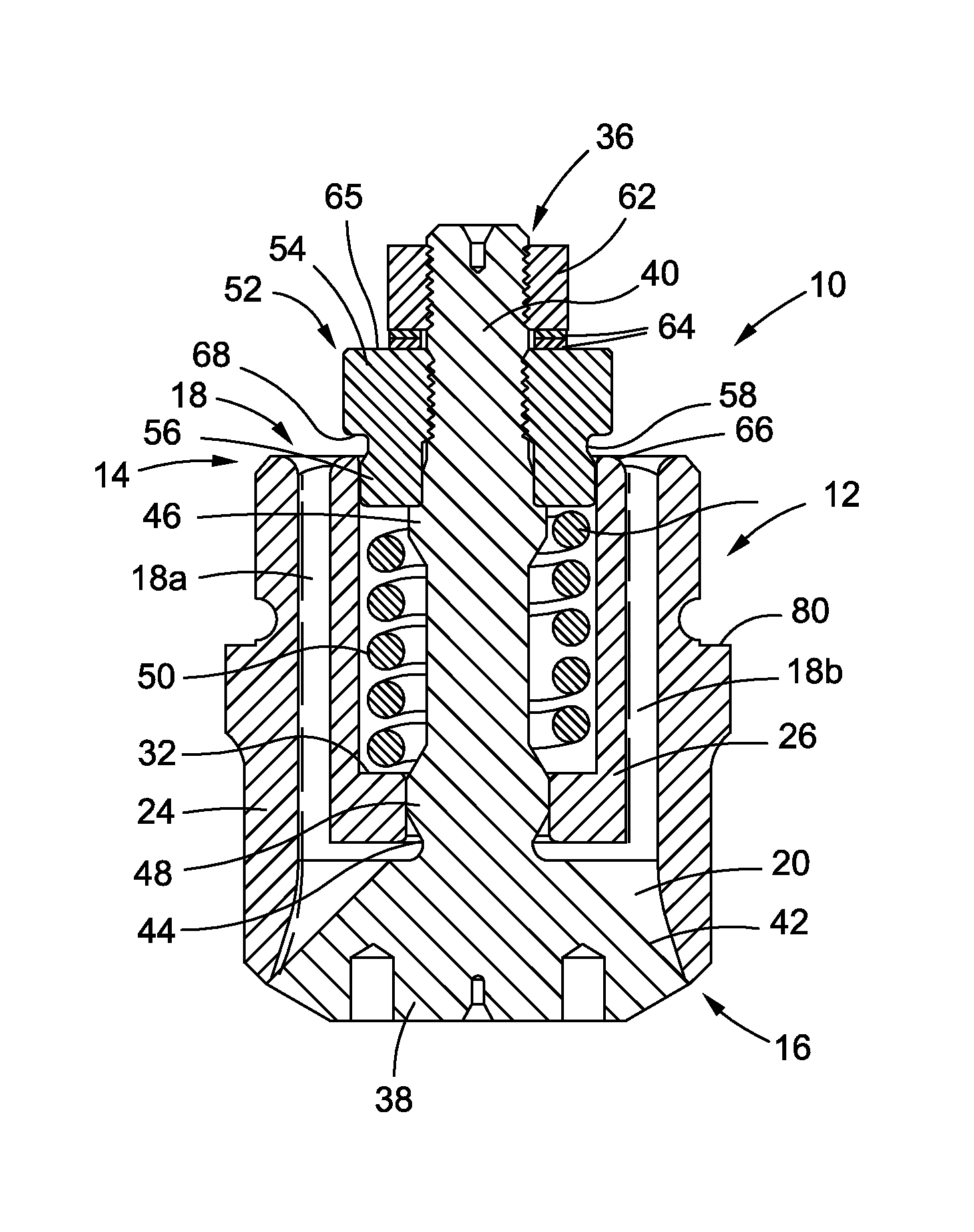
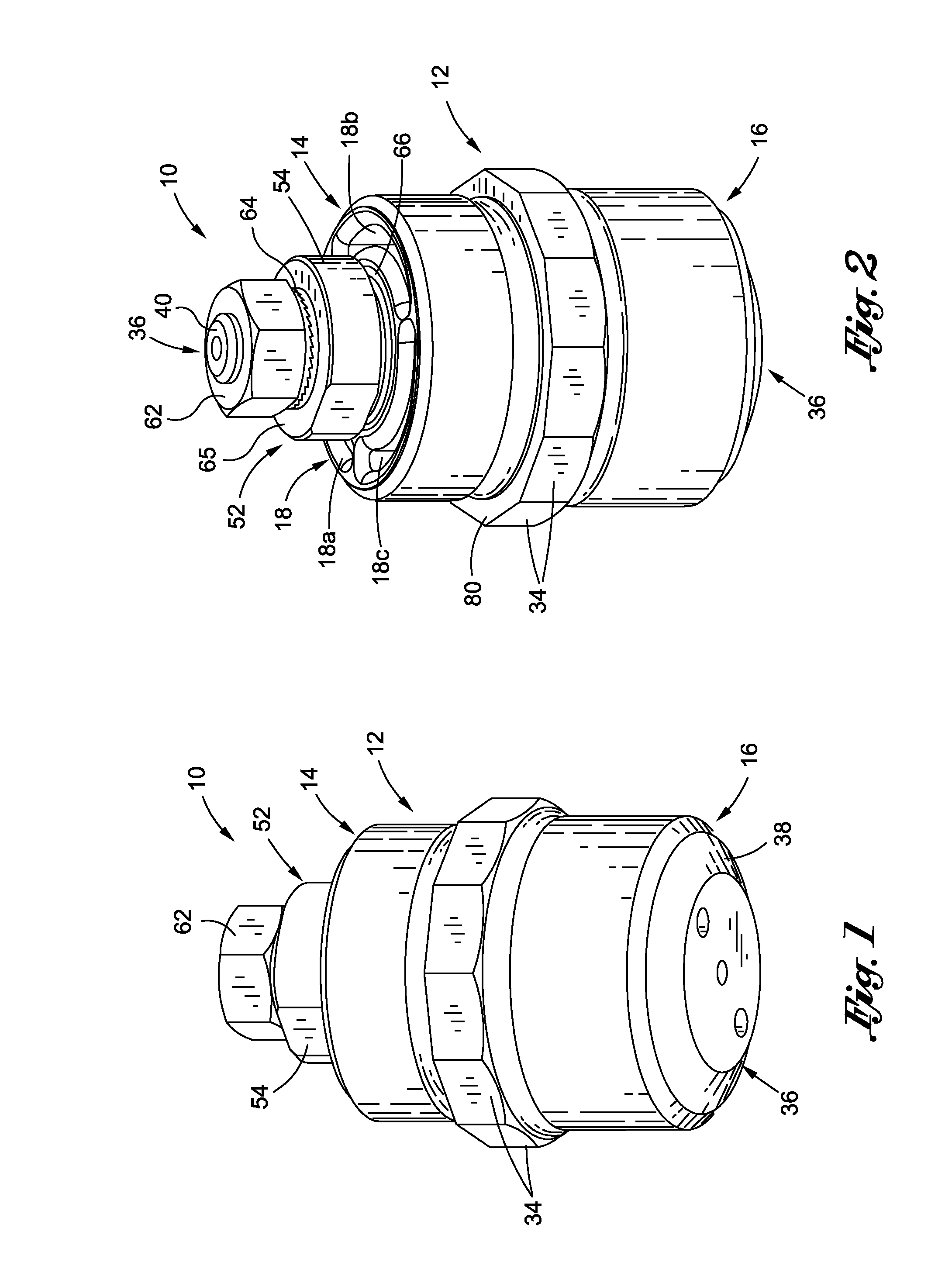
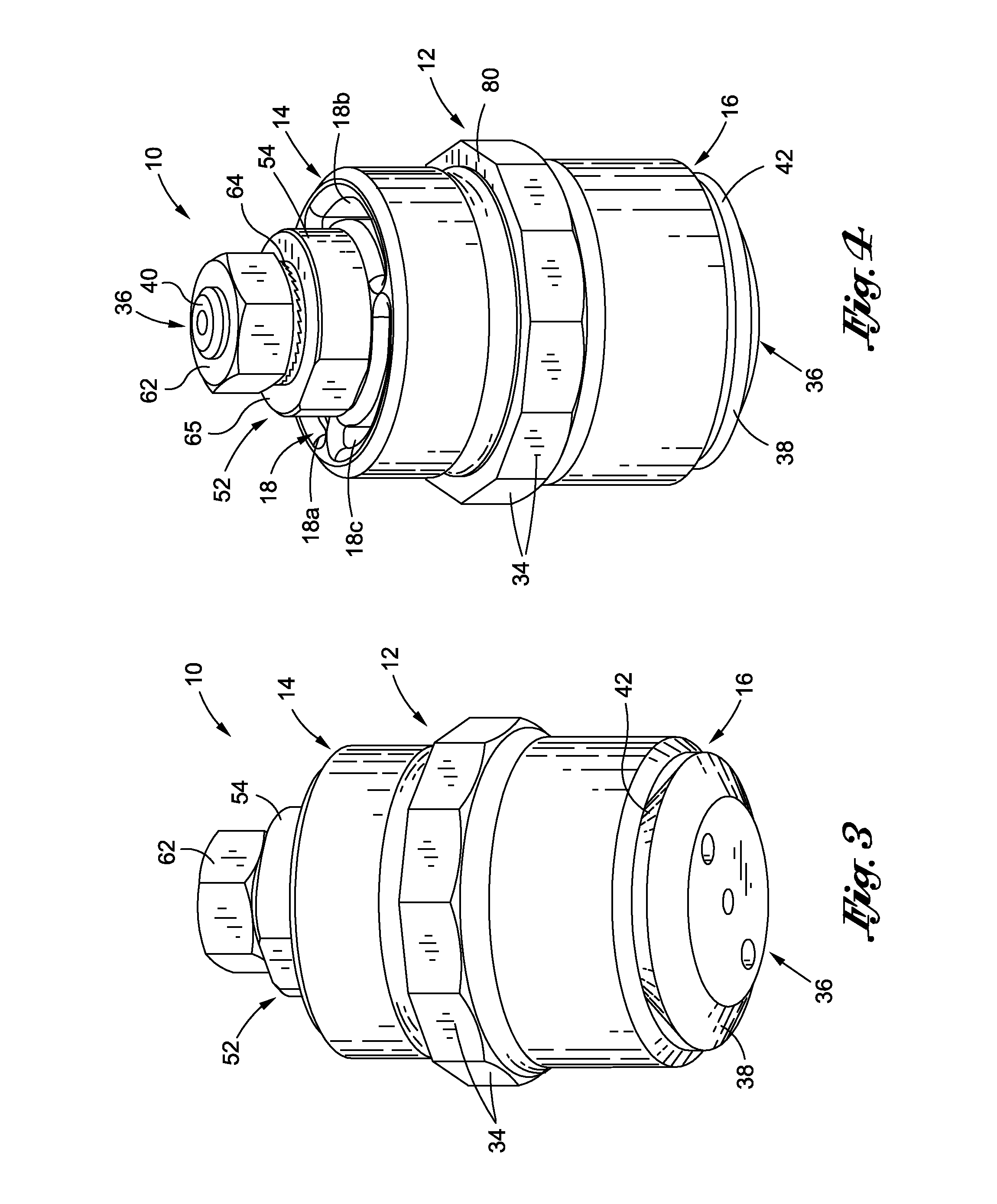
[0034]Referring now to the drawings wherein the showings are for purposes of illustrating preferred embodiments of the present invention only, and not for purposes of limiting the same, FIGS. 1-6 depict a nozzle assembly 10 constructed in accordance with the present invention. In FIGS. 1, 2 and 5, the nozzle assembly 10 is shown in a closed position which will be described in more detail below. Conversely, in FIGS. 3, 4 and 6, the nozzle assembly 10 is shown in an open position which will also be described in more detail below. As indicated above, the nozzle assembly 10 is adapted for integration into a desuperheating device such as, but not necessarily limited to, a probe type attemperator. As will be recognized by those of ordinary skill in the art, the nozzle assembly 10 of present invention may be integrated into any one of a wide variety of different desuperheating devices or attemperators without departing from the spirit and scope of the present invention.

[0035]The nozzle ass...

second embodiment

[0054]Referring now to FIGS. 12-14, there is shown a nozzle assembly 100 constructed in accordance with present invention. In FIG. 12, the nozzle assembly 100 is shown in a closed position which will be described in more detail below. Like the nozzle assembly 10 described above, the nozzle assembly 100 is adapted for integration into a desuperheating device such as, but not necessarily limited to, a probe type attemperator.

[0055]The nozzle assembly 100 comprises a nozzle housing 112 which is shown with particularity in FIG. 13. The nozzle housing 112 has a generally cylindrical configuration and, when viewed from the perspective shown in FIG. 13, defines a first, top end 114 and an opposed second, bottom end 116. The nozzle housing 112 further defines a generally annular flow passage 118. The flow passage 118 comprises three identically configured, arcuate flow passage sections 118a, 118b, 118c, each of which spans an interval of approximately 120°. One end of each of the flow passa...


PUM

PropertyMeasurementUnit
Angleaaaaaaaaaa
Diameteraaaaaaaaaa

Abstract

An improved spray nozzle assembly for use in a steam desuperheating device that is adapted to spray cooling water into a flow of superheated steam. The nozzle assembly is of simple construction with relatively few components, and thus requires a minimal amount of maintenance. In addition, the nozzle assembly is specifically configured to, among other things, prevent thermal shock to prescribed internal structural components thereof, to prevent “sticking” of a valve element thereof, and to create a substantially uniformly distributed spray of cooling water for spraying into a flow of superheated steam in order to reduce the temperature of the steam.

Description

CROSS-REFERENCE TO RELATED APPLICATIONS[0001]The present application is a continuation-in-part of U.S. patent application Ser. No. 13 / 644,049 entitled IMPROVED NOZZLE DESIGN FOR HIGH TEMPERATURE ATTEMPERATORS filed Oct. 3, 2012.STATEMENT RE: FEDERALLY SPONSORED RESEARCH / DEVELOPMENT[0002]Not ApplicableBACKGROUND OF THE INVENTION[0003]1. Field of the Invention[0004]The present invention pertains generally to steam desuperheaters or attemperators and, more particularly, to a uniquely configured spray nozzle assembly for a steam desuperheating or attemperator device. The nozzle assembly is specifically adapted to, among other things, prevent thermal shock to prescribed internal structural components thereof, to prevent “sticking” of a valve stem thereof, and to create a substantially uniformly distributed spray of cooling water for spraying into a flow of superheated steam in order to reduce the temperature of the steam.[0005]2. Description of the Related Art[0006]Many industrial facili...

Claims


Application Information

Patent Timeline
IPC IPC(8): F22G5/12
CPCF22G5/123B05B1/06B05B1/3006B05B1/304B05B1/3073Y10S261/13Y10T137/7932
Inventor WATSON, DANIEL ALLEN LEENEWTON, RAYMOND RICHARDFREITAS, STEPHEN GERALDNAZIRI, KEVIN
Owner CONTROL COMPONENTS INC
Why Eureka
Try Eureka