Mobile radio

a mobile radio and radio antenna technology, applied in the field of mobile radios, can solve the problems of poor matching, poor downsizing, and thicker mobile phone terminals, and achieve the effect of enhancing the antenna characteristics

Inactive Publication Date: 2005-05-24
PANASONIC INTELLECTUAL PROPERTY CORP OF AMERICA
View PDF14 Cites 19 Cited by
  • Summary
  • Abstract
  • Description
  • Claims
  • Application Information

AI Technical Summary

Benefits of technology

[0011]Therefore, an object of the present invention is to provide smaller-sized mobile radios in which their built-in antennas are high enough to enhance the antenna characteristics.

Problems solved by technology

However, the conventional mobile radio antenna structured as above has a problem that the larger height h0 results in the thicker mobile phone terminals, thus failing in downsizing.
This will result in poor matching, and accordingly lower the antenna characteristics.

Method used


Image

  • Mobile radio
  • Mobile radio
  • Mobile radio

Examples


first embodiment

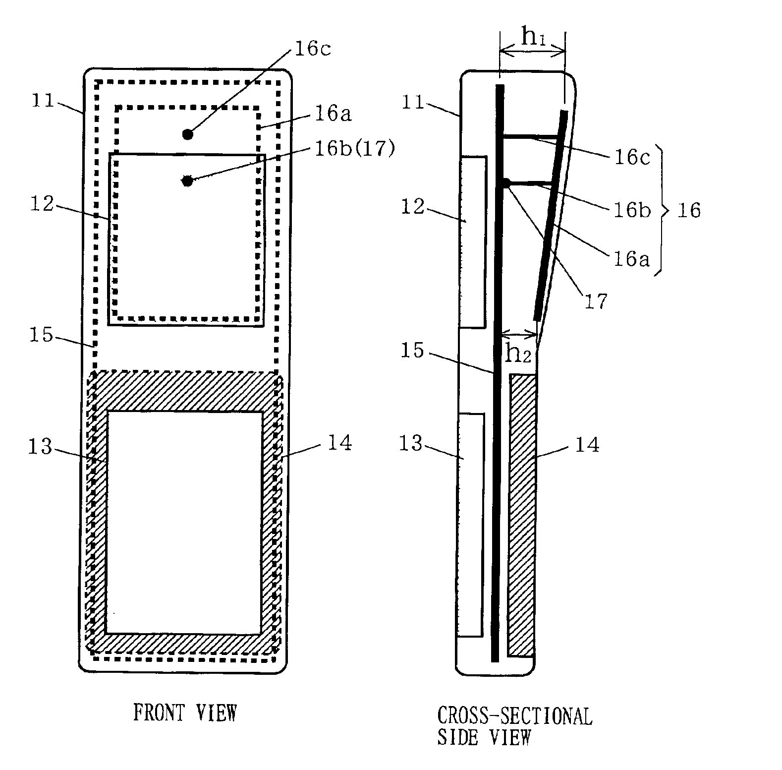
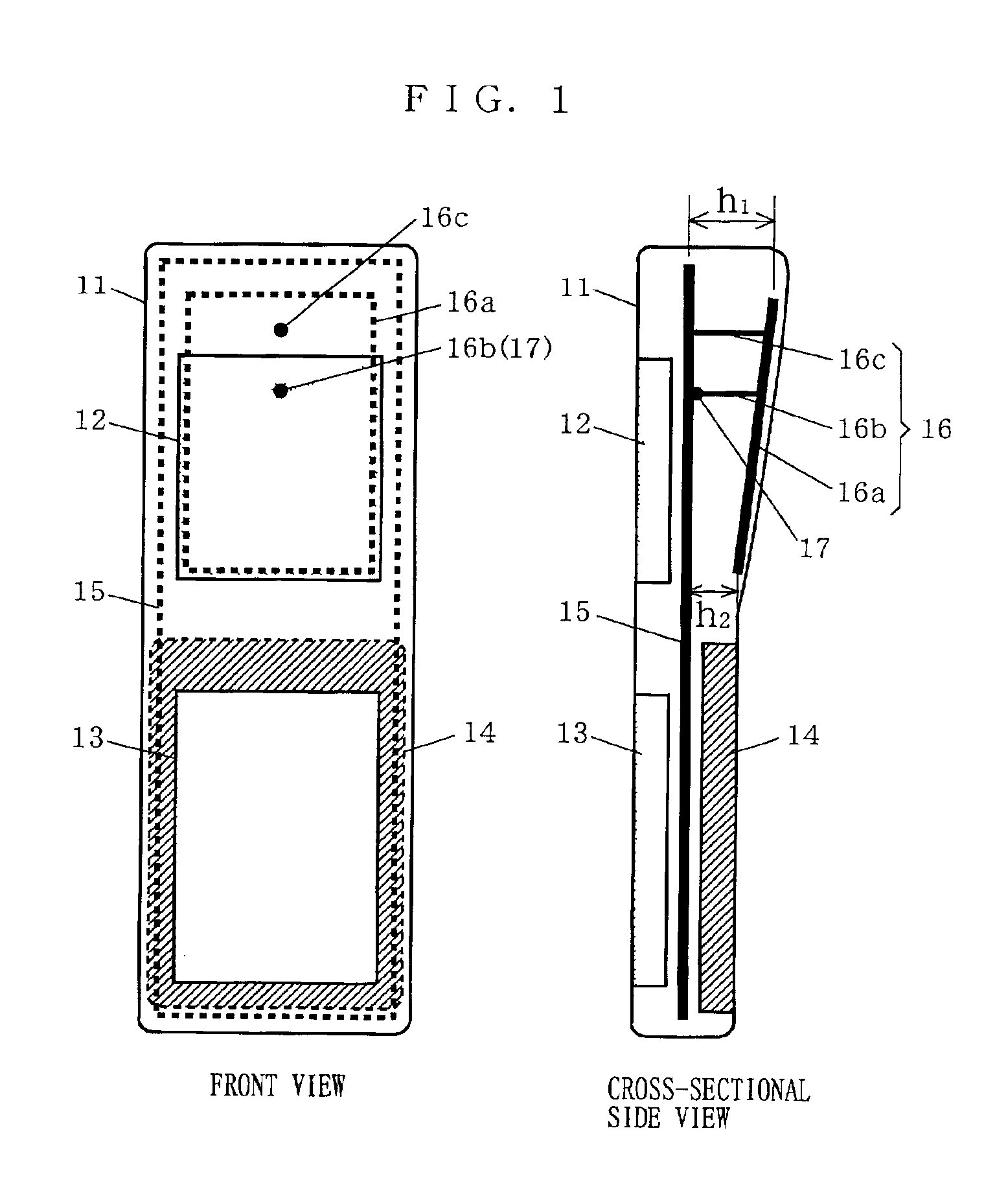
[0045]FIG. 1 schematically shows front and cross-sectional side views of a mobile radio according to a first embodiment of the present invention.

[0046]In FIG. 1, the mobile radio of the first embodiment includes a cabinet (case) 11, a display 12 exemplified by a liquid crystal display, a key section 13 exemplified by a ten-key numeric pad, a battery 14, a built-in antenna 16, and a base plate 15 for electrical connections among those constituents. The built-in antenna 16 is structured by an antenna element 16a of a planar configuration, and two metal leads 16b and 16c. The antenna element 16a is provided with a predetermined voltage from a supply point 17 on the base plate 15 via the metal lead 16b. The antenna element 16a is connected to a ground (GND) level of the base plate 15 via the metal lead 16c. Here, operating the GND pattern of a circuit board as the base plate is absolutely possible. Also, any cabinet or chassis made of conductive materials can be surely used as the base ...

second embodiment

[0058]FIG. 4 schematically shows front and cross-sectional side views of a mobile radio according to a second embodiment of the present invention.

[0059]In FIG. 4, the mobile radio of the second embodiment includes a cabinet (case) 31, a display 32 exemplified by a liquid crystal display, a key-section 33 exemplified by a ten-key numeric pad, a battery 34, a built-in antenna 36, and a base plate 35 for electrical connections among those constituents. The built-in antenna 36 is structured by an antenna element 36a of a planar configuration, and two metal leads 36b and 36c. The antenna element 36a is provided with a predetermined voltage from a supply point 37 on the base plate 35 via the metal lead 36b. The antenna element 36a is connected to a ground (GND) level of the base plate 35 via the metal lead 36c.

[0060]The base plate 35 is structured by an antenna-housing section which affects the antenna characteristics, and a circuit-housing section which is the rest of the base plate 35....


PUM


Abstract

A small-sized mobile radio has a built-in antenna is high enough to enhance the antenna characteristics. In the mobile radio, a base plate is structured by a section (antenna-housing section) including a supply portion and a short-circuiting portion, for example, of an antenna element which affect the antenna characteristics, and a section (circuit-housing section) which is the rest of the base plate. The antenna-housing section is so positioned so as to keep the built-in antenna high enough, that is, to keep the space between the base plate and the antenna element large enough. On the other hand, the circuit-housing section is positioned toward the back of the cabinet to provide room for a display and a key section.

Description

BACKGROUND OF THE INVENTION[0001]1. Field of the Invention[0002]The present invention relates to mobile radios and, more particularly, to mobile radios in which antennas are equipped for receiving and transmitting radio waves exemplified as mobile phone terminals.[0003]2. Description of the Background Art[0004]The technology relating to mobile communications which is commonly applied to mobile phones, for example, has recently seen a rapid growth. In such mobile phones, antennas are considered especially important, and in keeping with the mobile terminals getting smaller, the antennas are required to be downsized to fit therein.[0005]With reference to the accompanying drawing, described below is an exemplary mobile radio antenna conventionally equipped in mobile phone terminals.[0006]FIG. 8 schematically shows front and cross-sectional side views of a mobile phone terminal, e.g., mobile radio, which has a conventional mobile radio antenna equipped therein.[0007]In FIG. 8, the conven...

Claims


Application Information

Patent Timeline
Patent Type & Authority Patents(United States)
IPC IPC(8): H01Q9/04H01Q1/24H04B1/38
CPCH01Q1/243H01Q9/0471H01Q9/0442H01Q9/0421H04B1/38
Inventor IWAI, HIROSHIYAMAMOTO, ATSUSHIOGAWA, KOICHIKAMAEGUCHI, SHINJITAKAHASHI, TSUKASAYAMADA, KENICHI
Owner PANASONIC INTELLECTUAL PROPERTY CORP OF AMERICA
Why Eureka
Try Eureka