
Composite substrate for use in magnetic recording-and-reproducing device

a technology of magnetic recording and recording, applied in the direction of recording on magnetic tapes, instruments, printed circuit non-printed electric components, etc., can solve the problems of limiting the effective use of the main plate b>2, corner cutting cabinets, less pleasing appearance, etc., and achieves the effect of substantial area and little or no was

Inactive Publication Date: 2005-05-24
ORION ELECTRIC CO LTD
View PDF2 Cites 0 Cited by
  • Summary
  • Abstract
  • Description
  • Claims
  • Application Information

AI Technical Summary

Benefits of technology

[0014]The so shaped composite substrate permits full use of a square or rectangular board material of stated size, leaving little or no waste. Also, advantageously it has a substantial area available to installation of tall parts.

Problems solved by technology

Disadvantageously this limits the effective use of the main plate 2 to the non-overlapping area in respect of mounting tall parts.
Such corner-cut cabinet, however, is less pleasing in appearance.
This requires new molding dies, which cost so much that the amount saved by reducing substrate size (and accordingly increasing the number of substrates to be cut from a single board material) cannot compensate for the amount involved for making such new molding dies.

Method used


Image

  • Composite substrate for use in magnetic recording-and-reproducing device
  • Composite substrate for use in magnetic recording-and-reproducing device
  • Composite substrate for use in magnetic recording-and-reproducing device

Examples


Embodiment Construction

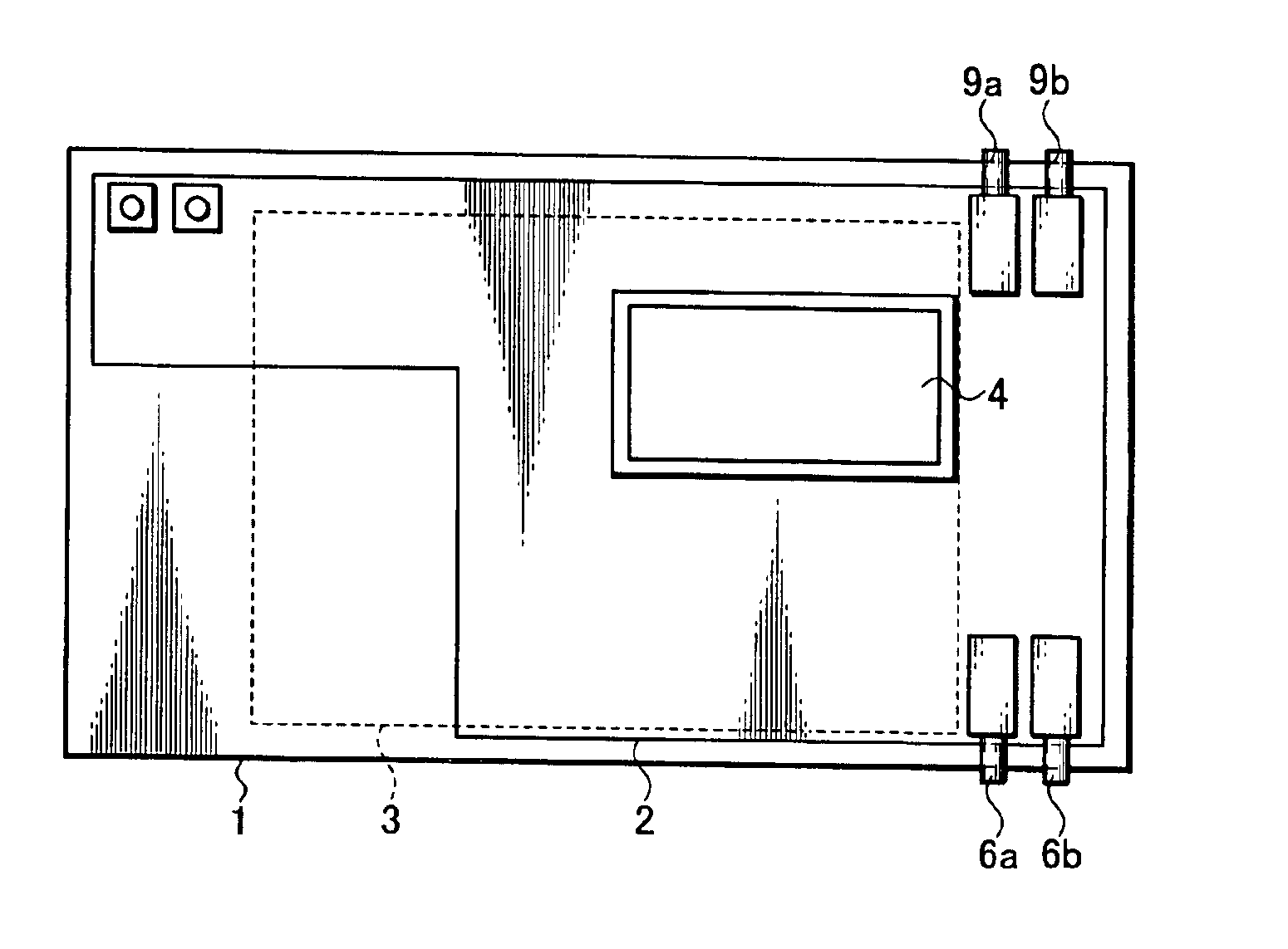
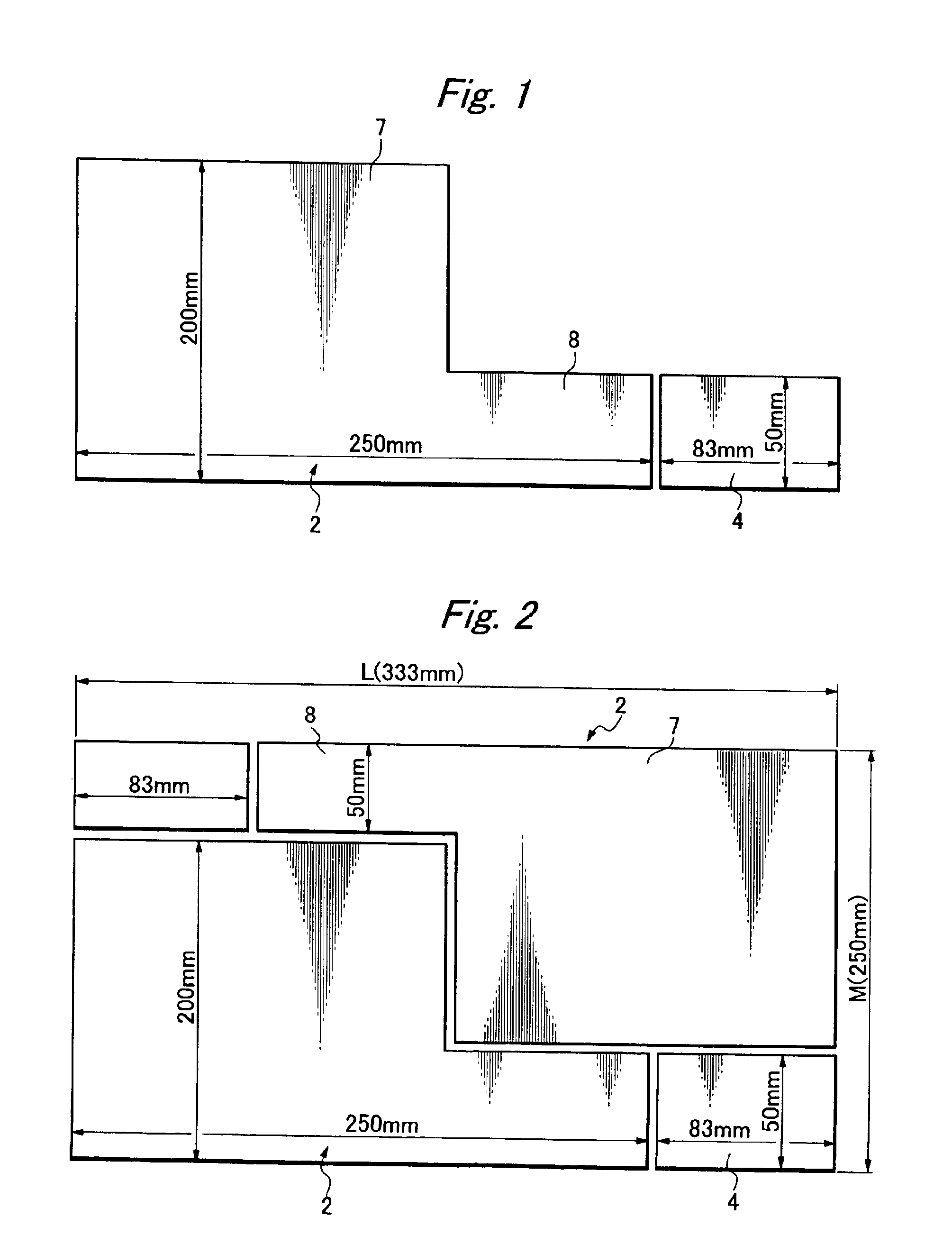
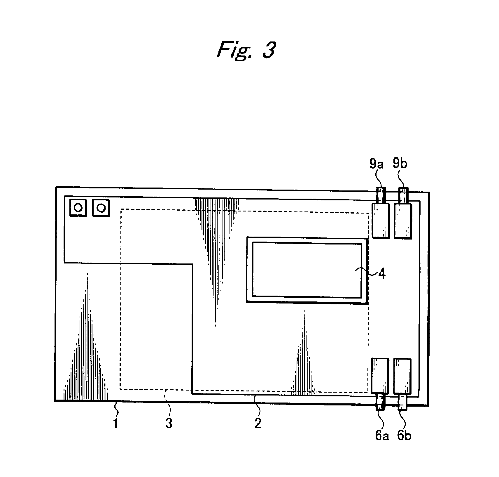
[0023]FIG. 1 shows a composite substrate for use in a magnetic recording-and-reproducing device according to the present invention. It comprises an “L”-shaped main plate 2 and a separate sub-plate 4. The “L”-shaped main plate 2 comprises a major section 7 of relatively large area and a minor section 8 of relatively small area, integrally connected to one side of the major section 7. The sub-plate 4 comprises a square or rectangular piece, which is cut and separated from the minor section 8. Such composite substrates can be cut from a square or rectangular board of stated size (for examples, 1,000 mm×1,000 mm or 1,000 mm×1,200 mm). A plurality of pairs of composite substrates are so drawn in the square or rectangular board material of stated size that each pair of substrates may be inversely arranged and jointed together to define a square or rectangular shape (see FIG. 2), and the square or rectangular board material of stated size is punched, leaving little or no waste.

[0024]For ex...


PUM

PropertyMeasurementUnit
sizeaaaaaaaaaa
sizeaaaaaaaaaa
areaaaaaaaaaaa

Abstract

Disclosed is an improved composite substrate for use in a magnetic recording-and-reproducing device. It comprises an “L”-shaped main plate and a separate sub-plate. The “L”-shaped main plate has a major section of relatively large area and a minor section of relatively small area, integrally connected to one side of the major section. The sub-plate has a square or rectangular piece cut and separated from the minor section of the main plate. When being inversely arranged and jointed together two composite substrates can define a square or rectangular shape.

Description

BACKGROUND OF THE INVENTION[0001]1. Field of the Invention[0002]The present invention relates to a composite substrate for use in a magnetic recording-and-reproducing device, which composite substrate comprises a main plate and a separate sub-plate.[0003]2. Related Art[0004]Magnetic recording-and-reproducing devices and other electronics include printed circuit boards each having a lot of electronic parts to provide electric circuits. Small-sized electric circuits can be efficiently fabricated by installing a large number of electronic parts in a substrate at an increased density, and, advantageously such installation can be automatized.[0005]As a general tendency different electronics have been reduced in size, and accordingly printed circuit boards used have been reduced in size. Downsizing of printed circuit boards meets the requirement for cost reduction, also.[0006]Incidentally, a number of printed circuit boards are cut from a square or rectangular board material of stated siz...

Claims


Application Information

Patent Timeline
Patent Type & Authority Patents(United States)
IPC IPC(8): G11B33/02H05K3/00H05K1/14
CPCG11B33/02H05K3/0052H05K1/141Y10T29/49135H05K2201/09027Y10T29/49021
Inventor MAEDA, MICHIHARU
Owner ORION ELECTRIC CO LTD
Learn More