
Method for estimating telephony system-queue waiting time in an agent level routing environment

a technology of agent level and waiting time, applied in the field of computer telephony integrated (cti) communication systems, can solve the problems of a call center system, a limited routing that can be done, and a limited range of computer processes in the current art of telephony switches, although increasingly computerized,

Inactive Publication Date: 2005-05-24
GENESYS TELECOMM LAB INC AS GRANTOR +3
View PDF5 Cites 75 Cited by
  • Summary
  • Abstract
  • Description
  • Claims
  • Application Information

AI Technical Summary

Problems solved by technology

If the call center consists of just a central switch and connected telephone stations, the routing that can be done is quite limited.
Current art telephony switches, although increasingly computerized, are limited in the range of computer processes that may be performed.
Even with present levels of CTI there are still problems in operating such call centers, or a system of such call centers.
While this technique helps to even out call loads among different queues, queue length may still be high during peak traffic periods.
However, a long queue can still be an irritating factor for many callers, even when some form of entertainment such as music is provided.
The above-described techniques may help to stabilize overall queue waiting times within call centers, or help to alleviate caller stress when waiting time is excessive, but they only partially address the problem.
Many callers who are not informed of an approximate waiting time will lose patience and terminate the call after a short wait if they believe that they will have to hold for much longer, even though in actuality, they may have terminated the call just prior to being transferred to an agent.
While the above mentioned system technically provides for informing callers of an estimated queue-waiting time, it is somewhat crude and limited in scope.

Method used


Image

  • Method for estimating telephony system-queue waiting time in an agent level routing environment
  • Method for estimating telephony system-queue waiting time in an agent level routing environment
  • Method for estimating telephony system-queue waiting time in an agent level routing environment

Examples


Embodiment Construction

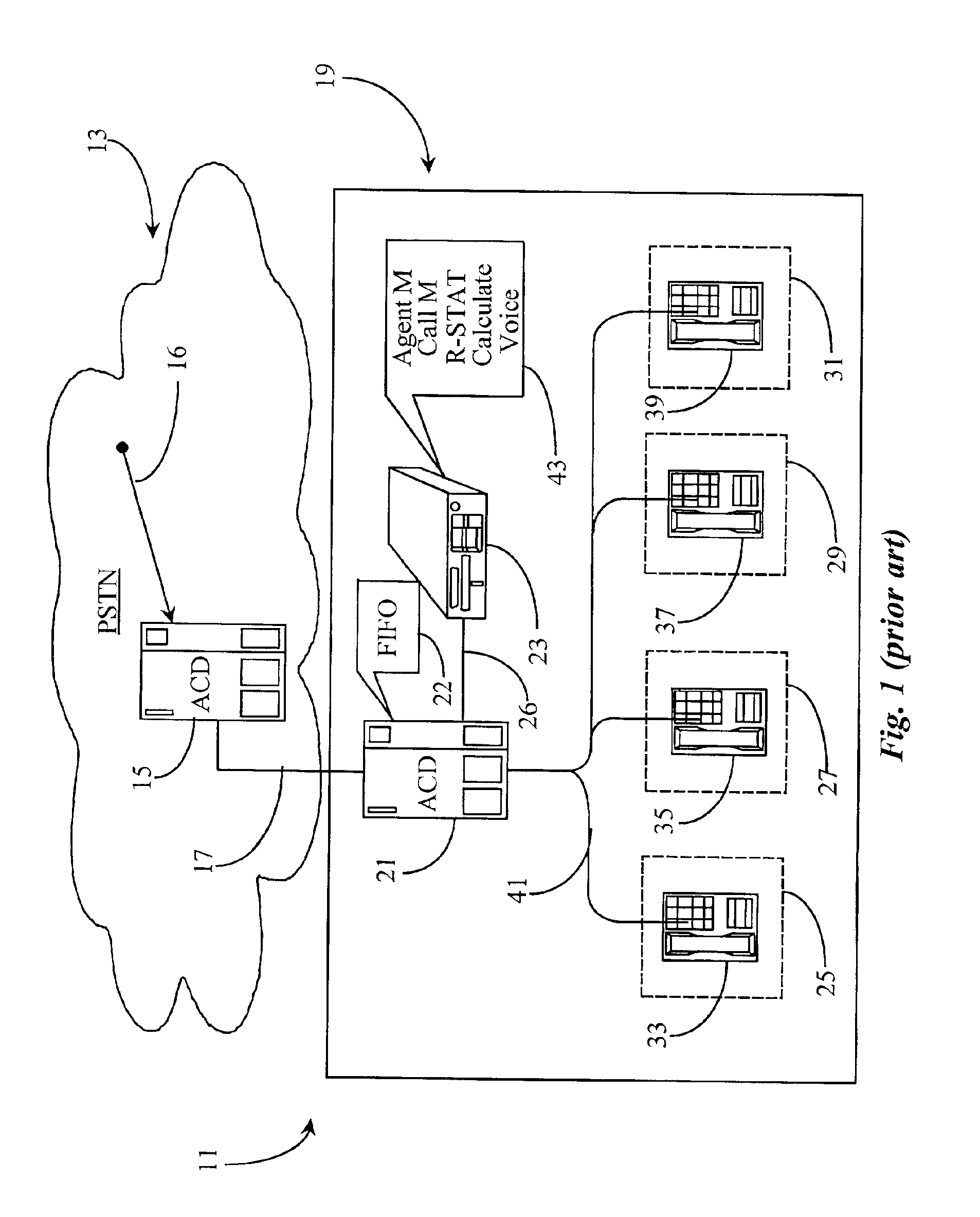
[0030]FIG. 1 is a block diagram illustrating a communication system 11 wherein calculation of estimated waiting time (EWT) is practiced according to the prior art. As previously mentioned in the background section, prior art attempts to estimate call waiting time in call-center queues is rather limited in scope. The prior art approach cited in U.S. Pat. No. 5,020,095 assumes a limited hardware-fix that is applicable only for an ACD system wherein strict FIFO queuing is practiced. To further illustrate limitation in this approach, a prior art overview is illustrated below.

[0031]Communication system 11 comprises a PSTN 13 and a call-in center 19. System 11 uses the well known ACD-type telephony switching common to a COST network. For example, PSTN 13 has an ACD switch 15 connected therein and adapted to receive incoming calls represented by a vector 16 from anywhere in PSTN 13. ACD 15 is connected to an ACD central switch 21 within call-in center 19 via telephony trunk 17. ACD 21 is a...


PUM


Abstract

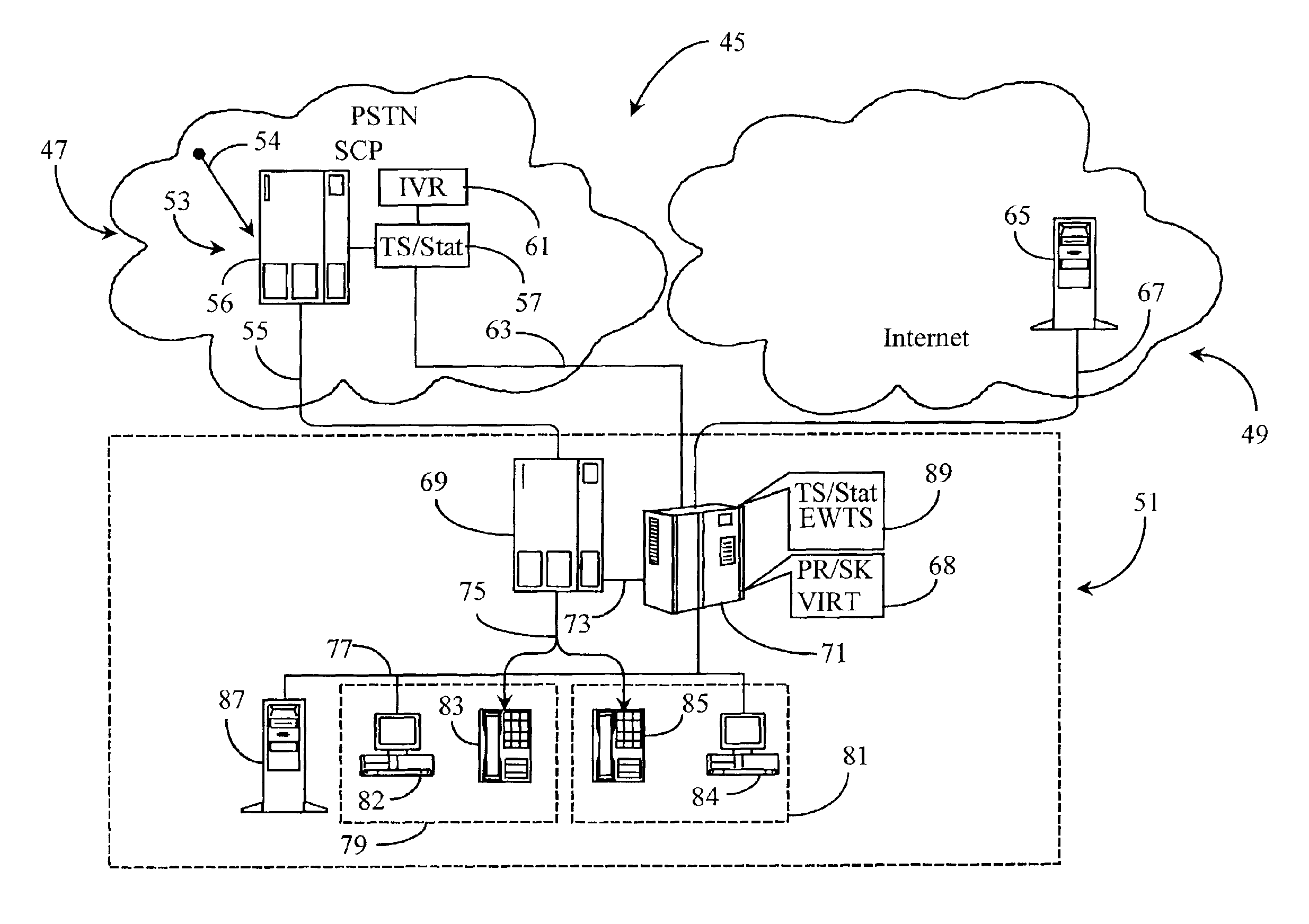
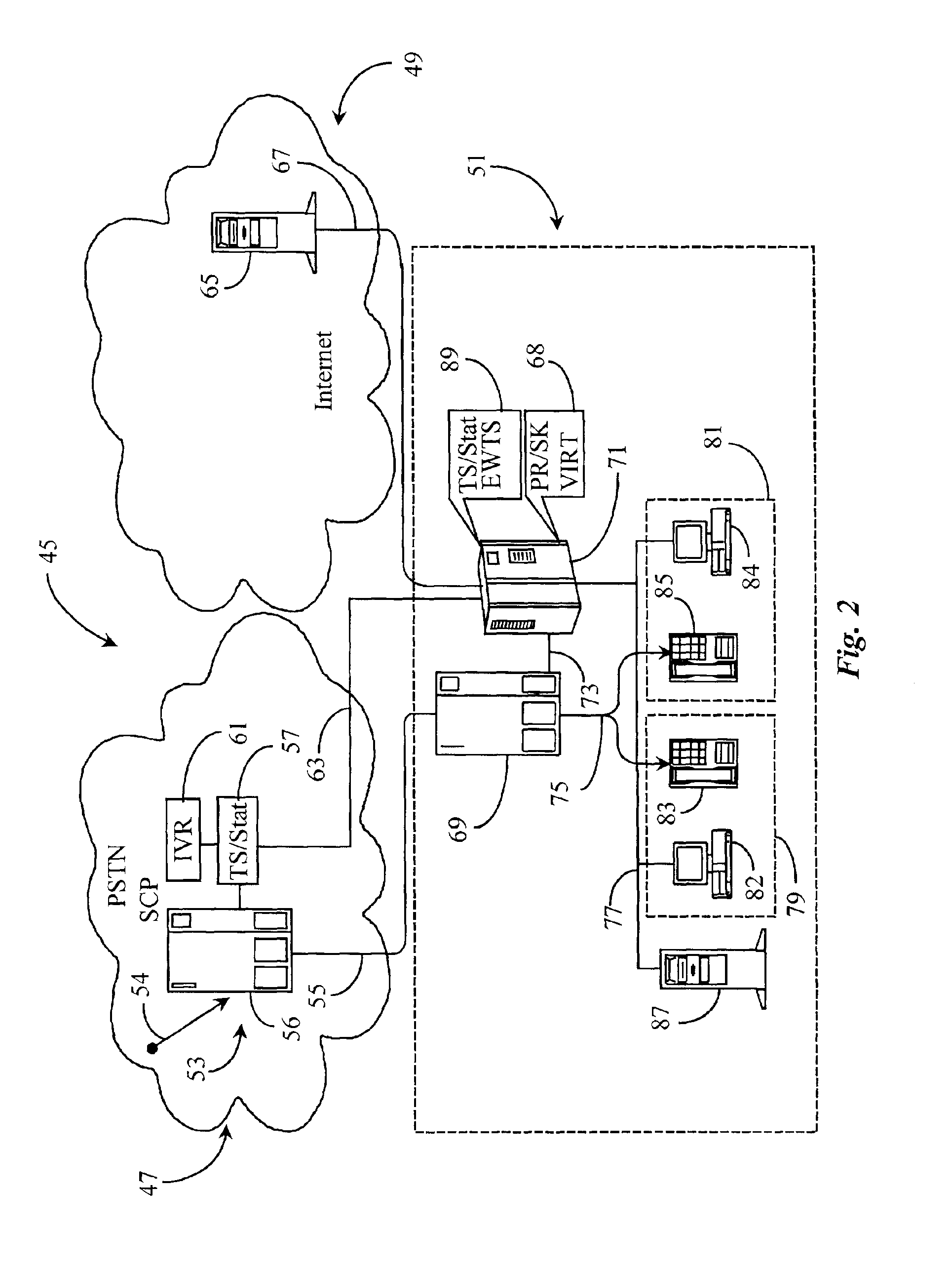
A system for estimating call waiting time for a call in a queue takes into account multiple queues wherein agents are shared between queues, abandoned call history, and virtual and priority queues. The system in a preferred embodiment is a computer-telephony integration (CTI) software application adapted to execute on a CTI processor, which may be coupled to switching equipment at network level in a connection-oriented, switched telephony (COST) network or to a switch at call-center level, or both.

Description

CROSS-REFERENCE TO RELATED DOCUMENTS[0001]The present application is a divisional application of patent application Ser. No. 09 / 209,306 filed Dec. 11, 1998, now U.S. Pat. No. 6,157,655. The prior application is incorporated herein by reference in its entirety.FIELD OF THE INVENTION[0002]The present invention is in the field of Computer Telephony Integrated (CTI) communication systems including both connection-oriented, switched telephony (COST) systems and Data Network Telephony (DNT) systems such as Internet-Protocol-Network-Telephony (IPNT) systems, and pertains more particularly to methods and apparatus for estimating call waiting time for queues in skill-based agent level routing (ALR) environments.BACKGROUND OF THE INVENTION[0003]Telephone call processing and switching systems are, at the time of the present patent application, relatively sophisticated, computerized systems, and development and introduction of new systems continues. Much information on the nature of such hardwa...

Claims


Application Information

Patent Timeline
Patent Type & Authority Patents(United States)
IPC IPC(8): H04M3/50H04M3/523H04M3/42H04M7/00H04L29/06H04M3/48H04M3/51H04M3/53H04M7/12H04M11/00H04Q3/62
CPCH04L29/06H04Q3/62H04M3/5191H04M3/523H04M3/5232H04M3/5237H04M3/48H04M3/5183H04M3/5231H04M3/5235H04M3/5238H04M3/5307H04M7/0006H04M7/0009H04M7/12H04M2201/50H04M2207/12H04M3/42323H04M7/0033H04L9/40
Inventor SHTIVELMAN, YURIANISIMOV, NIKOLAY A.POGOSSIANS, GREGORYDERYUGIN, VLADIMIR N.BALKIN, DMYTRO G.STOILOV, LUBEN GUEORGUIEV
Owner GENESYS TELECOMM LAB INC AS GRANTOR
Learn More