Method and system for component compatibility verification

a technology of component compatibility and verification method, applied in the field of automatic software and/or hardware compatibility verification, can solve the problems of increasing the requirement for compatibility and the risk of errors, the complexity of system upgrades, and the time and resources consumed in system upgrades planning,

Inactive Publication Date: 2005-05-24
CISCO TECH INC
View PDF7 Cites 51 Cited by
  • Summary
  • Abstract
  • Description
  • Claims
  • Application Information

AI Technical Summary

Benefits of technology

[0010]In yet another aspect of the invention, a control module in a switch first verifies itself to determine if its associated hardware revision and one or more associated software revisions are compatible with one another based on compatibility information for the control module provided in a predetermined compatibility matrix. After the control module successfully verifies itself, the control module verifies each of one or more related service modules to determine if the control module is compatible with the one or more related service modules based on compatibility information for the control module and for the one or m

Problems solved by technology

System upgrades can be a complex process requiring much planning.
Planning for system upgrades is an activity that can consume time and resources.
With each new release of a component, the requirement for compatibility and risk of errors increase.
Even with detailed compatibility d

Method used


Image

  • Method and system for component compatibility verification
  • Method and system for component compatibility verification
  • Method and system for component compatibility verification

Examples


Embodiment Construction

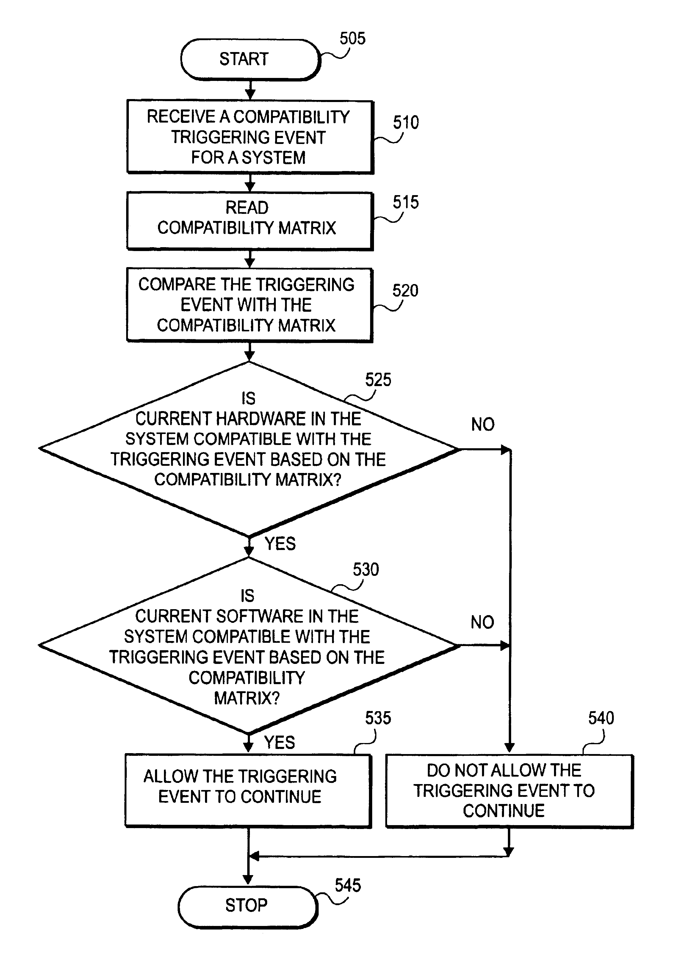
[0022]In one embodiment of the invention, a compatibility matrix is formed to provide compatibility information for a plurality of components in a system. Responsive to a change associated with a component in the system, the change is automatically compared with the compatibility information to determine whether to accept the change or to reject the change.

[0023]In the following description, for purposes of explanation, numerous specific details are set forth in order to provide a thorough understanding of the present invention. It will be evident, however, to one skilled in the art that the present invention may be practiced without these specific details. In other instances, well-known structures, processes and devices are shown in block diagram form or are referred to in a summary manner in order to provide an explanation without undue detail.

[0024]FIG. 3 is a diagram illustrating an example of a compatibility map in accordance with one embodiment of the present invention. The co...


PUM


Abstract

Components to be verified for compatibility are identified. Each of the components maintains a relationship with the other components such that all of the components are compatible with one another. A change to one component triggers an automatic evaluation of the relationships between the changed component and the other components to determine if compatibility is maintained. The automatic evaluation of the relationships is based on predetermined compatibility information provided in a compatibility matrix. When the automatic evaluation identifies incompatibility between the changed component and the other components, the change is rejected.

Description

FIELD OF THE INVENTION[0001]The present invention relates generally to field of system maintenance and migration, more specifically directed to automatic software and / or hardware compatibility verification.BACKGROUND[0002]System upgrades can be a complex process requiring much planning. Typically, system upgrades are performed to replace failing hardware or to take advantages of new or enhanced features of current hardware. The new or enhanced features may come in the form of hardware, software or a combination of both hardware and software. One important requirement to be addressed in performing system upgrades is compatibility of the new hardware with the existing hardware and software in the system. Planning for system upgrades is an activity that can consume time and resources. Often documentations are meticulously prepared and followed to avoid potential negative impact on the system.[0003]For example, in the MGX 8850 switch manufactured by Cisco Systems of San Jose, Calif., th...

Claims


Application Information

Patent Timeline
IPC IPC(8): G06F9/46G06F9/445G06F17/50
CPCG06F8/65G06F17/50G06F9/465G06F2217/86G06F30/00G06F2117/08
Inventor THEODOSSY, SAMERYELLAI, PRABHAKARATRUONG, ALEXSTEBBINS, ROBERTMEDVED, JAN
Owner CISCO TECH INC
Why Eureka
Try Eureka