Adaptable cab floor engagement assembly for commuter and conventional jet aircraft

a technology for cabs and jet aircraft, which is applied in the direction of bridges, chutes, constructions, etc., can solve the problem of accommodating the operator of a conventionally constructed bridg

Inactive Publication Date: 2005-05-31
FMC CORP +1
View PDF59 Cites 25 Cited by
  • Summary
  • Abstract
  • Description
  • Claims
  • Application Information

AI Technical Summary

Benefits of technology

[0020]The first, second and third floor panels may be each rotated by a respective driving structure. Each of these floor panels is rotatable independent of the other floor panels to permit the cab floor assembly operator to vary the configuration of the cab floor and thereby adapt the cab floor to the particular construction of the aircraft portal structure being presently serviced by the boarding bridge.

Problems solved by technology

The fact that commuter aircraft doors pivot about a horizontal axis creates a number of complications for the operator of a conventional boarding bridge structure which has been designed for use with aircraft having doors which pivot about a vertical axis.
The operator of a conventionally constructed bridge is confronted with the problem of accommodating the boarding bridge to a door having upstanding structure which is not a conventional feature of doors found on commercial aircraft.

Method used


Image

  • Adaptable cab floor engagement assembly for commuter and conventional jet aircraft
  • Adaptable cab floor engagement assembly for commuter and conventional jet aircraft
  • Adaptable cab floor engagement assembly for commuter and conventional jet aircraft

Examples


Embodiment Construction

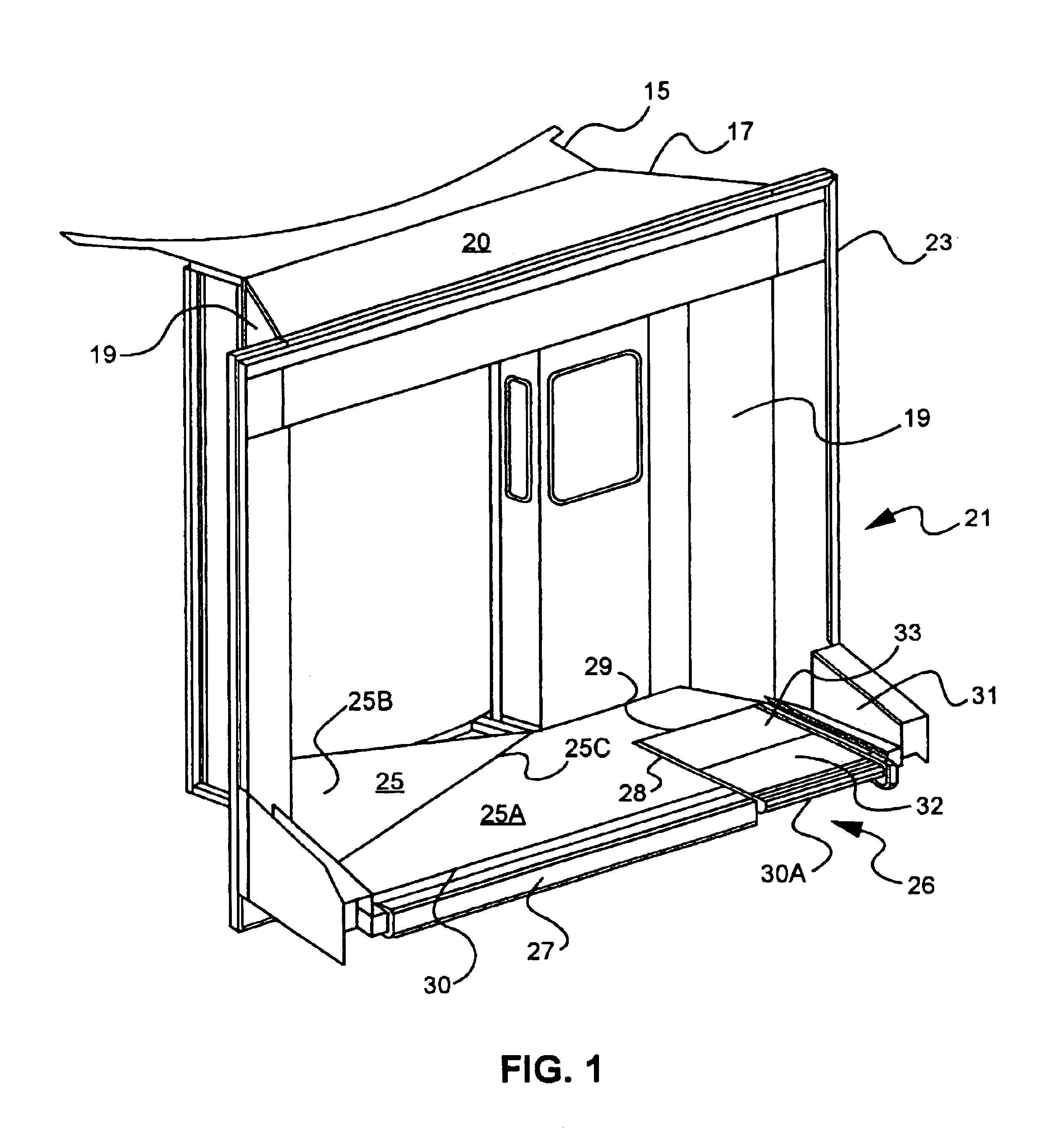
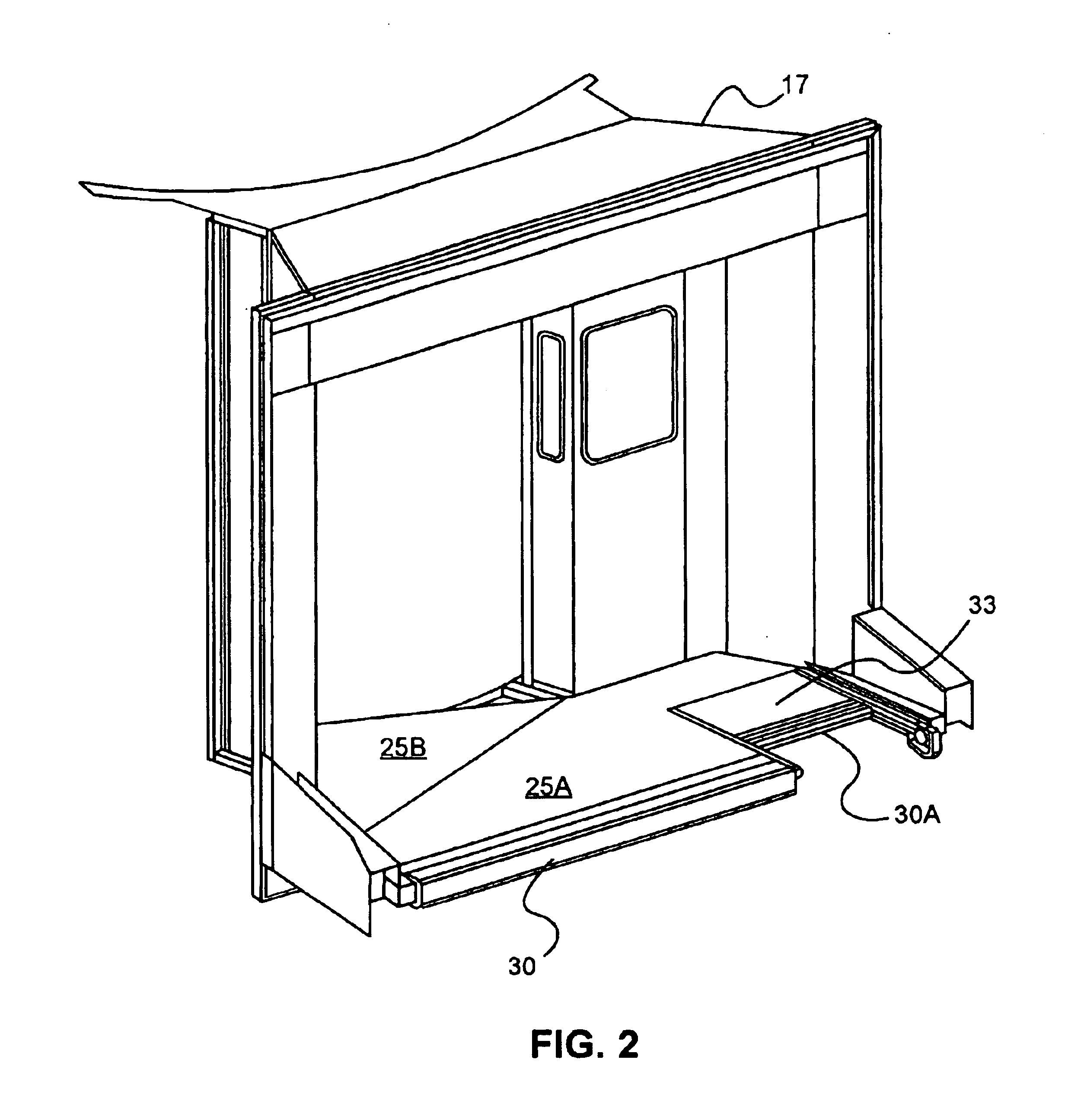
[0059]As illustrated in FIG. 1, a boarding bridge 15 (shown in partial view) is fitted on its outer end with a cab 17. The cab 17 is a generally enclosed structure having a pair of opposingly positioned upstanding sidewalls 19 surmounted by a ceiling or roof element 20 which extends between the two sidewalls. The cab further includes a floor element 25. The floor element 25 extends between the two sidewalls. The cab also defines an entryway from the main boarding bridge structure. The cab 17 defines an open portal 21 which is designed to interface with the fuselage of the aircraft to be serviced by the boarding bridge. The portal 21 is defined by a framing structure 23 which extends upwardly from the floor 25 in a generally inverted U-shaped configuration. The portal frame 23 may be fitted with a canopy structure (not shown) which extends from the frame to contact the fuselage of the aircraft. A conventional accordion-like canopy is anticipated for this purpose.

[0060]The floor 25 is...


PUM


Abstract

An engagement structure adapted for securement to the end of an aircraft boarding bridge includes a floor, a first floor panel rotatably associated with the floor, and a second floor panel displaceably associated with the floor. The second floor panel is preferably mechanically associated with a drive assembly adapted for displacing the second floor panel relative to the first floor panel to provide a dimensionally adjustable floor area of a boarding bridge proximate the interface of the bridge and an aircraft serviced by the bridge. The engagement structure is adapted to accommodate the docking of the boarding bridge with aircraft having varied entry door configurations.

Description

CROSS-REFERENCE TO RELATED APPLICATION[0001]Pursuant to the provisions of 35 U.S.C. 119(e), this application claims the benefit of the filing date of provisional patent application Ser. No. 60 / 238,169, filed 5 Oct. 2000, for “Adaptable Cab Floor Engagement Assembly For Commuter and Conventional Jet Aircraft.”BACKGROUND OF THE INVENTION[0002]1. Field[0003]This invention relates to apparatus for use in servicing aircraft at airports. More specifically, the invention is directed to aircraft boarding bridges which are adapted for permitting egress from and ingress to an aircraft positioned adjacent to an airport terminal building.[0004]2. Statement of the Art[0005]Aircraft boarding bridges have become a commonplace phenomena at airport terminals both in this country and abroad. Such bridges provide a passageway for aircraft passengers and crew from the terminal building to an aircraft parked proximate to the terminal building. These bridges are highly valued for their ability to shelter...

Claims


Application Information

Patent Timeline
Patent Type & Authority Patents(United States)
IPC IPC(8): B64F1/305B64F1/00
CPCB64F1/3055
Inventor THOLEN, TRENT D.WEST, GLEN O.POHLY, DANIEL D.CHASE, THOMASJENSEN, KENNETHWOFFORD, CATHARINEHANSEN, CHRIS
Owner FMC CORP
Why Eureka
Try Eureka