Prefabricated foam block concrete forms with open tooth connection means

a technology of connecting means and foam blocks, which is applied in the direction of forms/shuttering/falseworks, shaping building parts, walls, etc., can solve the problems of block design that requires work site assembly, water and other debris is trapped in the socket, and no means are provided to allow such debris and water to be removed

Inactive Publication Date: 2008-08-12
AIRLITE PLASTICS
View PDF88 Cites 19 Cited by
  • Summary
  • Abstract
  • Description
  • Claims
  • Application Information

AI Technical Summary

Benefits of technology

[0013]Any block configuration will include an opposing pair of foam panels which are integrally connected together and held in spaced apart configuration by a plurality of ties positioned therebetween. A single array or row of alternating teeth and sockets are formed along opposing horizontal longitudinal edges of each panel to enable it to removably engage either opposing horizontal longitudinal edge of an adjacent vertically positioned panel having a substantially identical array of teeth and sockets formed along either longitudinal edge thereof. A substantially flat surface is located adjacent the single array of alternating teeth and sockets on each opposed horizontal longitudinal edge of each opposed panel forming the present block form, the substantially flat surface providing a means for allowing water and other debris to escape and not to be trapped in the sockets or spaces formed between the teeth. This promotes a better joinder between adjacent panels and facilitates a stronger and more stable wall structure when a plurality of the present block forms are interconnected to form a wall structure. This also improves the insulating capabilities of the present block forms.
[0014]In a preferred block form arrangement, the single array of alternating teeth and sockets associated with each opposing horizontal longitudinal edge of each opposed panel is positioned and located along the inside edge portion of each panel adjacent the space formed therebetween for receiving the fluid concrete. As a result, the substantially flat surface located adjacent the single array of alternating teeth and sockets is positioned along the outside edge portion of each panel thereby providing a path for any water and / or other debris which may accumulate within the alternating sockets to freely migrate away from and exit such sockets or spaces so that a tight seal and joinder can be achieved between the interlocking teeth and sockets associated with adjacent panels. The present substantially flat surface associated with each opposed horizontal longitudinal edge of each panel may also be tapered to further facilitate the removal of water or other debris which may accumulate within the alternating sockets. Similarly, arrays of alternating teeth and sockets are formed along opposing vertical end edges of each panel to enable one panel to removably engage either opposing vertical end of an adjacent horizontally positioned panel having a substantially identical array of teeth and sockets formed along either vertical end edge.
[0015]As a result, a planar block of the present invention can vertically and horizontally engageably receive adjacent whole or half planar or corner blocks of the present invention, regardless of the vertical orientation with respect to its horizontal longitudinal axis and regardless of the horizontal orientation with respect to its vertical axis. Likewise, a corner block of the present invention can vertically and horizontally engageably receive adjacent whole or half planar or corner blocks of the present invention, regardless of the vertical orientation with respect to its horizontal longitudinal axis and regardless of the horizontal orientation with respect to its vertical axis. The corner block of the present invention can, therefore, function as a left corner block or a right corner block, as well as provide two functional half corner block units when the corner block is divided along its horizontal midpoint. Other blocks having varying angular relationships between planar segments are likewise recognized and anticipated. To facilitate separating a block of planar or angular configuration along its horizontal midpoint, the outer surface of either opposing panel of each block is pre-marked along its horizontal midpoint.
[0017]The web has a plurality of rebar retaining seats formed thereon so that a rebar rod or member can be gravitationally placed within a given seat regardless of vertical orientation of the associated whole or half, planar, corner, or other angularly constructed block with respect to its horizontal longitudinal axis. The rebar retaining seats of each tie are of sufficient dimension to allow an unstraight rebar member to be retained therein without imparting undesirable torque forces to the tie member. Furthermore, the seat dimensions allow for overlapping ends of longitudinally adjacent rebar members to be retained therein to create, in effect, a wireless contact splice when the ends are imbedded in hardened concrete.
[0018]The corner block of the present invention includes a corner tie having a pair of corner flanges connected to a structural web member, all of which are encapsulated within a foam outer corner panel member to which exterior siding or facade will be attached. A concrete-engaging member extends inwardly from the structural web of the corner tie beyond the inner surface of the outer corner panel to serve as an anchor, when surrounded by concrete poured between opposing corner panels, to prevent the corner tie from being ripped from the corner foam block unit when exterior siding is anchored thereto.

Problems solved by technology

Such block designs have the disadvantage of requiring work-site assembly.
The interlocking mechanisms associated with many of the prior art ICF designs also include spaces or sockets formed between the teeth or projection patterns associated therewith wherein water, contaminants, and other debris can accumulate and can be trapped during installation and construction of a wall structure using an ICF system.
Since these ICF forms are exposed to inclement weather during installation at a particular site, water and other debris becomes trapped in the sockets and spaces formed between the connection means and no means are provided for allowing such debris and water to be removed or to escape prior to connecting adjacent ICF forms.
If water and / or debris is allowed to remain in such spaces or sockets, the integrity of the joinder between two adjacent ICF forms is compromised since such water and / or debris hinders and interferes with a good solid connection between adjacent ICF forms.
This not only weakens the joinder since a full and tight seat cannot be achieved between adjacent ICF forms, but it also affects the insulation capabilities of the ICF forms since cracks and other spaces may exist between adjacent forms due to the trapped and accumulated water and debris.
Also, depending upon the time of year, trapped water may also freeze and cause other structural instability problems.
Weakening of the joinder connection between two adjacent ICF forms due to trapped water and / or debris can likewise cause the wall structure formed by the ICF system to be displaced due to the outward forces created when concrete is poured therebetween.
However, in most prior art designs, in the event that it is necessary to remove the top half of the block along the horizontal midpoint, the top half of the block becomes unusable waste, due to the fact that these ties are not used with foam blocks that are designed to be vertically reversibly interlocking with adjacent blocks.
Furthermore, these prior art tie designs fail to optimize distribution of the flow of fluid concrete across the web portion of the tie.
Rather, they serve to impede even distribution of the fluid concrete between the foam panels.

Method used


Image

  • Prefabricated foam block concrete forms with open tooth connection means
  • Prefabricated foam block concrete forms with open tooth connection means
  • Prefabricated foam block concrete forms with open tooth connection means

Examples


Embodiment Construction

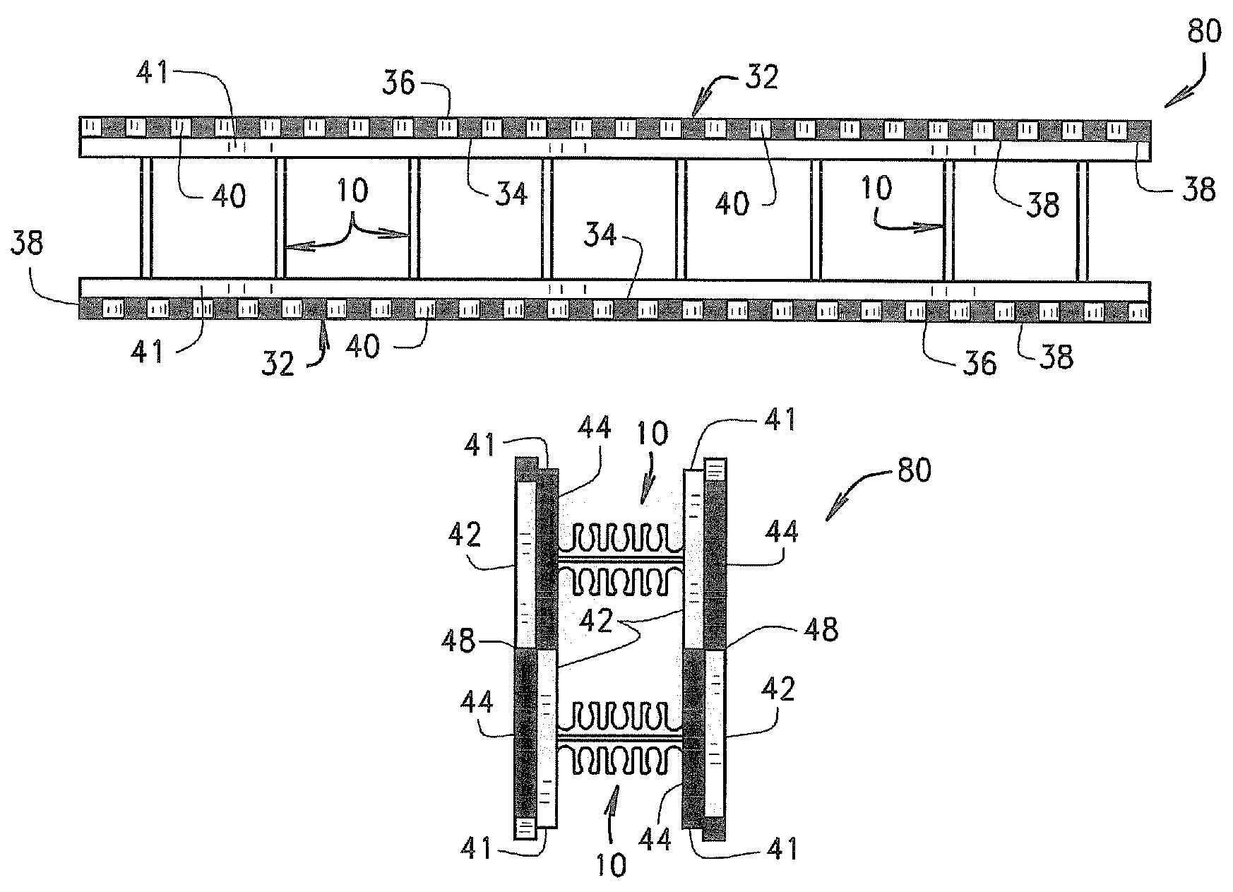
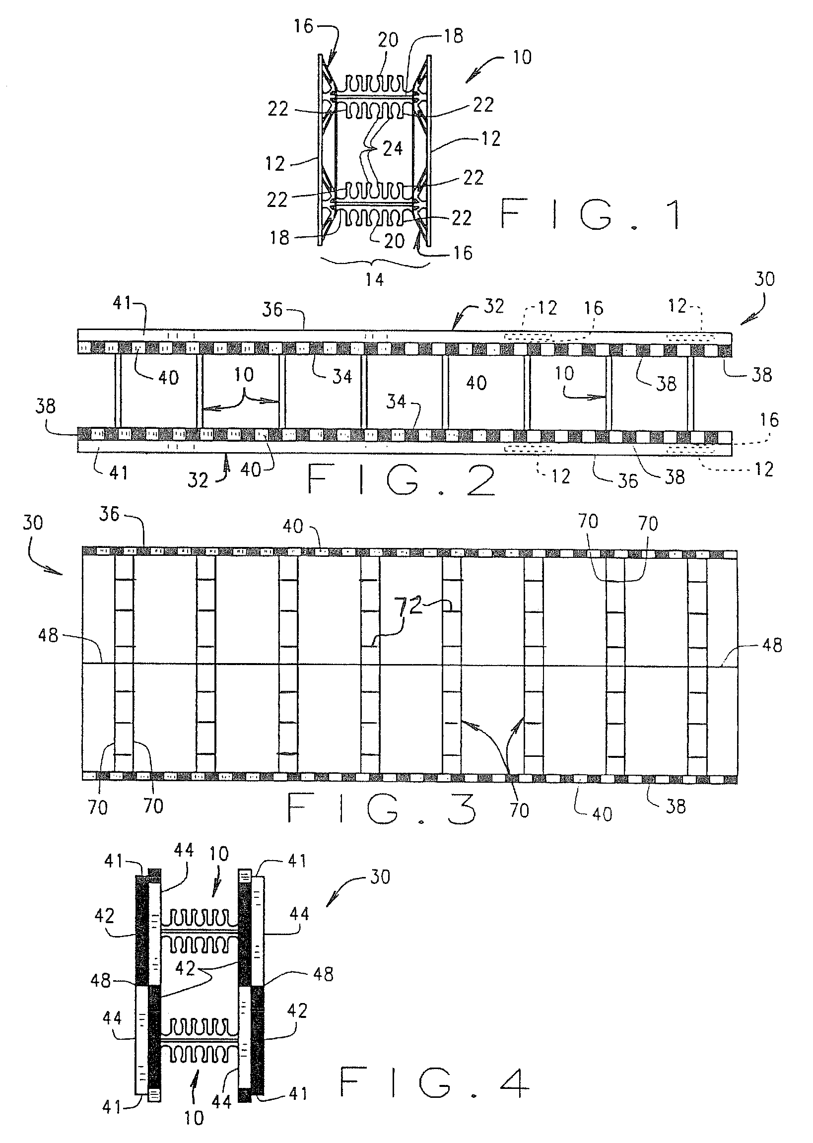
[0029]One embodiment of a form tie 10 of the present invention is illustrated in FIG. 1. The tie 10 includes a pair of flange members 12 separated by, and connected to, a web portion 14. The web portion 14 includes a pair of opposing truss members 16 connected by a pair of substantially identical transverse bridge members 18 having a plurality of rebar retaining seats 20 molded therein. In a preferred embodiment, the tie 10 is constructed from polypropylene. In other embodiments, the tie is constructed of metal, or other suitable materials.

[0030]The rebar seats 20 are substantially identical to each other in configuration, and are arranged in a pair of opposing rows along each transverse bridge 18. Each seat 20 includes a substantially U-shaped well formed by a pair of adjacent fingers 22. An inwardly spanning lateral knuckle or projection 24 is formed on the distal end of each pair of adjacent fingers 22, creating a distance between opposing projections 24 that is substantially les...


PUM


Abstract

A foam block concrete form including a pair of opposing foam panels spaced parallel from each other, a plurality of ties positioned transverse to and between the pair of opposed panels for holding the panels in spaced apart parallel relationship to each other, a single row of alternating teeth and sockets positioned and located along opposing horizontal longitudinal edges of each panel to enable the panels to be removably engaged with either opposed horizontal longitudinal edge of an adjacent vertically positioned panel having a substantially identical array of teeth and sockets formed along its opposed horizontal longitudinal edges, and a substantially flat planar surface located adjacent the single row of alternating teeth and sockets thereby providing a mechanism for facilitating the removal of water and other debris which may accumulate within the sockets or spaces formed between the teeth. The substantially flat surface may also be tapered to further facilitate the removal of water and other debris from within the alternating sockets.

Description

CROSS-REFERENCE TO RELATED APPLICATION[0001]This patent application claims priority to U.S. Provisional Patent Application Ser. No. 60 / 521,230 filed Mar. 16, 2004.BACKGROUND OF THE INVENTION[0002]The present invention relates to Insulating Concrete Form systems utilizing foam block forms and, more specifically, to improvements to the foam panels, the foam corner panels and the interlocking connection means associated therewith.[0003]Insulating Concrete Form (ICF) systems are known and serve to both contain fluid concrete while it solidifies and provide insulation for the finished structure. Such systems utilize a plurality of individual units, panels or blocks aligned horizontally and vertically in an interlocking arrangement to create forms for concrete walls. Each block comprises a pair of foamed panels which are retained in a spaced relationship parallel to each other by a plurality of ties.[0004]The spacing ties are truss-like and include opposing flange portions which reside wi...

Claims


Application Information

Patent Timeline
Patent Type & Authority Patents(United States)
IPC IPC(8): E04B2/86E04B1/16E04B2/00E04B2/02E04B5/04E04C1/41E04C2/04E04G11/06
CPCE04B2/8635E04C1/41E04B2002/867E04B2002/0217
Inventor PFEIFFER, HENRY E.
Owner AIRLITE PLASTICS
Why Eureka
Try Eureka