Electrical connection method

US6039238AInactive Publication Date: 2000-03-21WATLOW ELECTRIC MFG

Image

  • Electrical connection method
  • Electrical connection method

Examples


Embodiment Construction

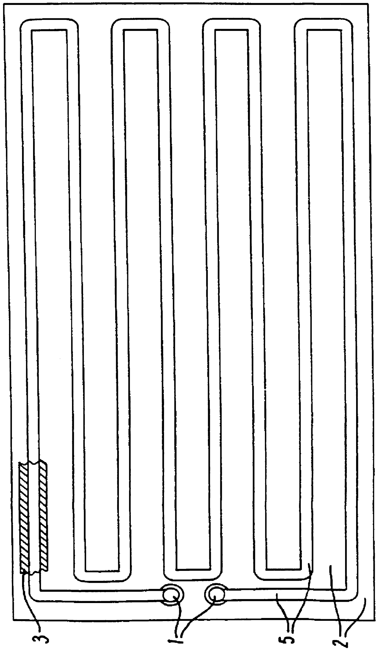
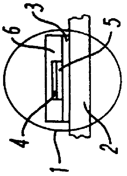
Referring to the drawing a ceramic track 3, only a part of which is shown in FIG. 1, is printed on a steel substrate 2. A heater track 5 is printed on the ceramic track 3. The heater track is, as shown, narrower than the ceramic track. The ceramic track 3 is only necessary if electrical insulation is needed between the heater track and the external environment for the purposes of protection both for the user and the heater track. The heater track terminates in pads 1 to which terminals 4 are connected by the application of pressure and ultrasonic welding at preferably 20 to 40 kHz. The termination can be protected by ceramic cover 6 if desired. If desired, a temperature sensor (not shown) can also be included with the heater on the substrate. The sensor is provided with pads to which connection can be made by the method of the invention in order to obtain the data provided by the sensor.

The method of the present invention can provide an electrical connection to a terminal or pad on ...


PUM

PropertyMeasurementUnit
Melting pointaaaaaaaaaa
Frequencyaaaaaaaaaa
Frictionaaaaaaaaaa

Abstract

PCT No. PCT / GB95 / 02626 Sec. 371 Date Sep. 19, 1997 Sec. 102(e) Date Sep. 19, 1997 PCT Filed Nov. 10, 1995 PCT Pub. No. WO96 / 17405 PCT Pub. Date Jun. 6, 1996A method of making an electrical connection stable over a wide temperature range between terminals on a metal or ceramic substrate comprising applying pressure to the connection and ultrasonically welding the terminals together.

Description

1. Field of the InventionThe present invention relates to a method of forming electrical connection and in particular to a method of forming an electrical connection with improved integrity and stability over a wide temperature range.2. Description of the Prior ArtVarious methods of forming electrical connections are known such as soldering, welding or the use of electrically conductive epoxy adhesives.There are, however, problems in forming a suitable high integrity electrical connection between terminals and a terminal pad which is deposited on a substrate such as metal, steel or ceramic or a substrate comprising one or more metal, steel or ceramic components or layers. Most conventional methods and materials used for attaching terminals have an upper temperature limit beyond which the original characteristics no longer hold so that electrical connections so formed are incapable of maintaining their attachment integrity over a wide temperature range.All known prior art methods of ...

Claims


Application Information

Patent Timeline
21 Mar 2000
Publication
US6039238A
IPC
B23K20/10; H01R43/02; H01R4/02
CPC
B23K20/10; H01R43/0207
Inventors
PANAGHE, STYLIANOS