Extraction cleaning with heating

a heating and extraction technology, applied in carpet cleaners, carpet/fur/leather cleaners, detergent compounding agents, etc., can solve the problems of steam systems suffering from poor cleaning performance, unsafe inclusion of detergents and the like in cleaning solutions, and further hindering cleaning performan

Inactive Publication Date: 2005-05-31
BISSELL INC
View PDF70 Cites 62 Cited by
  • Summary
  • Abstract
  • Description
  • Claims
  • Application Information

AI Technical Summary

Benefits of technology

[0016]In a further embodiment, the fluid dispensing system includes a valve having an inlet connected to the at least one fluid supply tank and a pair of outlets. A first fluid tube and a second fluid tube are connected to the valve outlets. The valve is adapted to selectively control the

Problems solved by technology

Because the steam is airborne, it may be unsafe to include detergents and the like in the cleaning solution.
However, the steam systems suffer from poor cleaning performance

Method used


Image

  • Extraction cleaning with heating
  • Extraction cleaning with heating
  • Extraction cleaning with heating

Examples


Embodiment Construction

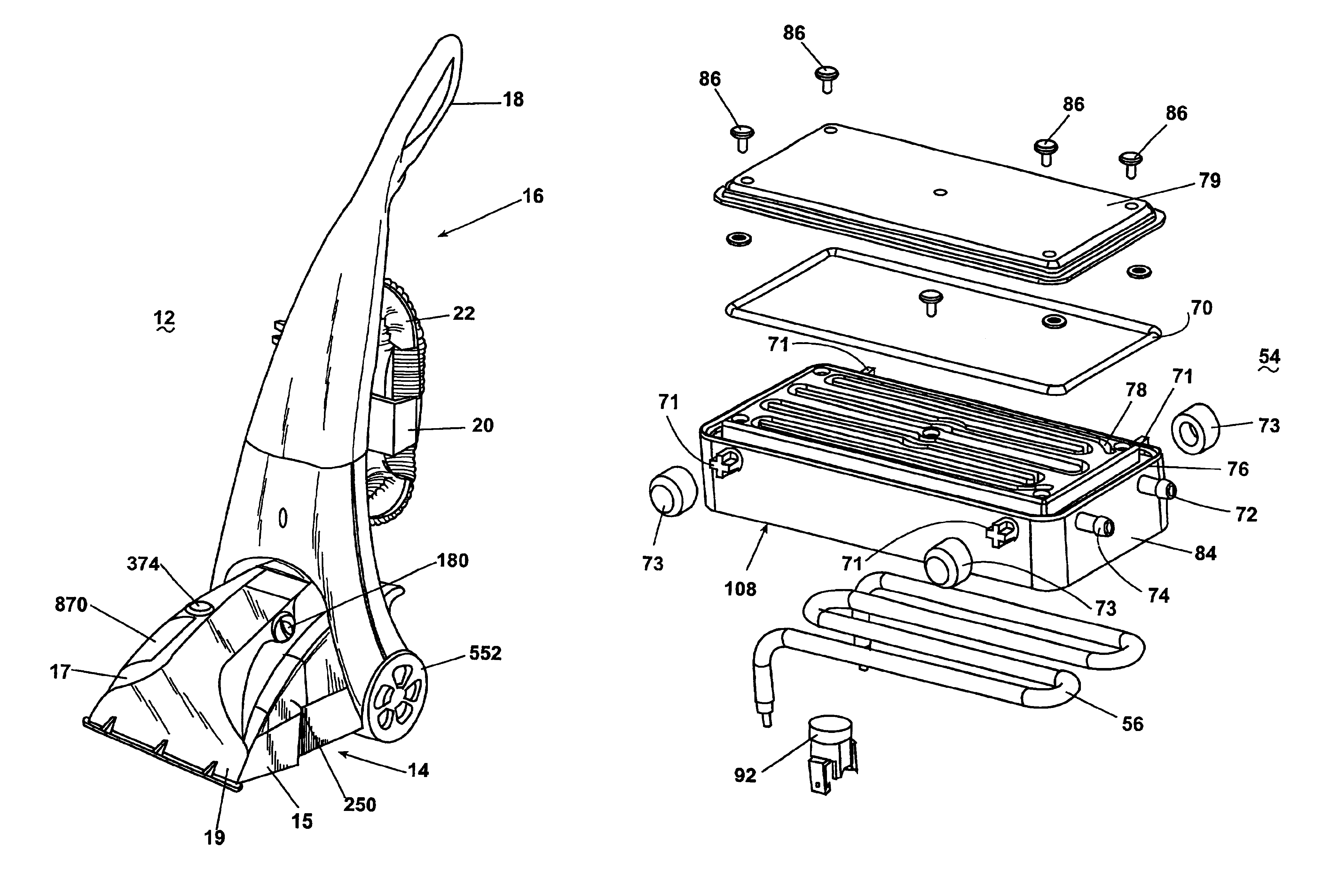
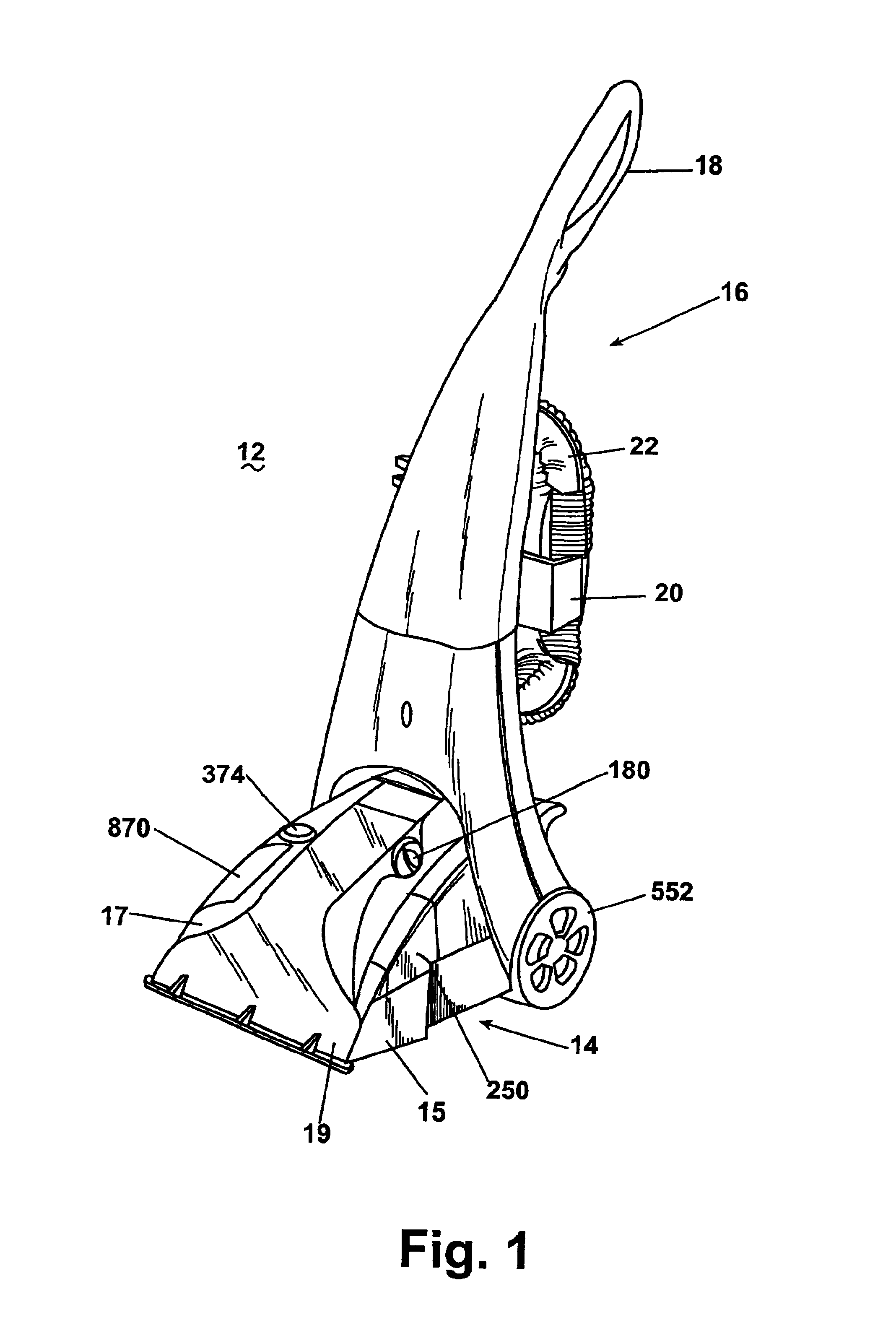
[0053]Referring now to the drawings and to FIG. 1 in particular, a first embodiment of an upright extraction cleaning machine 12 according to the invention is shown. The machine 12 is a portable surface cleaning apparatus including a base module 14 adapted to roll across a surface to be cleaned and an upright handle assembly 16 pivotally mounted to a rear portion of the base module 14.

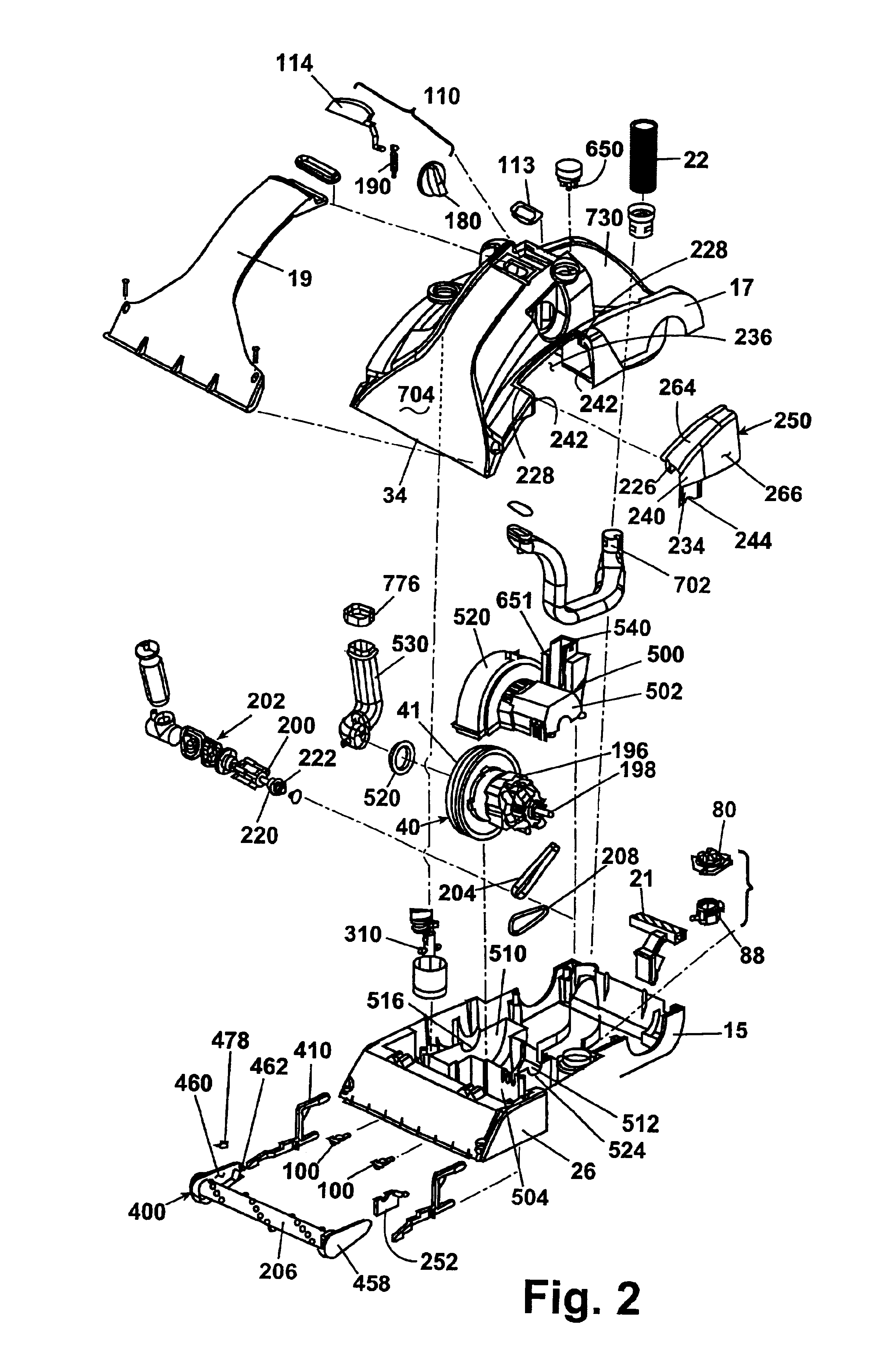
[0054]As best shown in FIGS. 1-3, the base module 14 includes a lower housing portion 15 and an upper housing portion 17, which together define an interior for housing components and a well 730 for receiving a tank assembly 50. Further, a well 732 in the upper housing portion 17 receives a detergent supply tank 870, as best shown in FIG. 3. The upper housing portion 17 receives a transparent facing 19 for defining a first working air conduit 704 and a suction nozzle 34, which is disposed at a front portion of the base module 14 adjacent the surface being cleaned for recovering fluid therefrom. The hand...


PUM

PropertyMeasurementUnit
Temperatureaaaaaaaaaa

Abstract

A portable surface cleaning apparatus comprises a fluid dispensing system including at least one fluid supply tank, a dispensing nozzle for applying a cleaning fluid to a surface to be cleaned, and a block heater for heating the fluid to be applied to the surface to be cleaned to a temperature less than boiling; a fluid recovery tank for holding recovered fluid; a suction nozzle; a working air conduit extending between the recovery tank and the suction nozzle; and a vacuum source in fluid communication with the recovery tank for generating a flow of working air from the suction nozzle through the working air conduit and into the recovery tank to thereby recover fluid from the surface to be cleaned.

Description

CROSS REFERENCE TO RELATED APPLICATIONS[0001]This application is a continuation of pending application Ser. No. 09 / 589,973, filed Jun. 8, 2000, which is a continuation in part of application Ser. No. 09 / 133,832, filed Aug. 13, 1998, now U.S. Pat. No. 6,131,237, which is a continuation in part of application Ser. No. 09 / 112,527, filed Jul. 8, 1998, entitled UPRIGHT EXTRACTION CLEANING MACHINE, now U.S. Pat. No. 6,167,587, and claims the benefit of U.S. Provisional Application Ser. No. 60 / 075,924, filed on Feb. 25, 1998, U.S. Provisional Application Ser. No. 60 / 052,021, filed on Jul. 9, 1997, U.S. Provisional Application Ser. No. 60 / 055,510, filed on Aug. 13, 1997, and U.S. Provisional Application Ser. No. 60 / 068,269, filed on Dec. 19, 1997, all of which are incorporated herein by reference.BACKGROUND OF THE INVENTION[0002]1. Field of the Invention[0003]This invention relates to an extraction cleaning machine. In one of its aspects, the invention relates to an extraction cleaning mach...

Claims


Application Information

Patent Timeline
IPC IPC(8): A47L11/00A47L11/40A47L11/34
CPCA47L5/30H05B3/00A47L7/0009A47L7/0028A47L7/0038A47L7/0042A47L11/30A47L11/34A47L11/40A47L11/4005A47L11/4008A47L11/4041A47L11/4044A47L11/4086A47L11/4088A47L11/4094B01F3/088C11D3/0031C11D3/39C11D3/3905C11D3/3947C11D7/3254C11D11/007C11D17/049F16K31/54A47L5/32C11D3/3917B01F23/49
Inventor KASPER, GARY A.MCDOWELL, DAVID E.
Owner BISSELL INC
Why Eureka
Try Eureka